Introduzione
Segui questa guida per sostituire il digitizer rotto o danneggiato della Nintendo Switch Lite.
La Switch utilizza delle viti JIS, ma all'occorrenza puoi usare un cacciavite Phillips. Stai molto attento a non spanare le viti. Le punte Phillips di iFixit sono progettate per essere compatibili anche con le viti JIS.
Nota: Questa guida è solo per il digitalizzatore. Se l'LCD smette di funzionare, potresti aver bisogno solo di sostituire quello, piuttosto che il digitalizzatore. Se stai sostituendo lo schermo (l'LCD collegato al digitalizzatore), segui questa guida.
Nota: Questa procedura richiede la rimozione della piastra di schermatura e il dissipatore. La pasta termica andrà pulita da entrambe le componenti, oltre che dalla CPU, e riapplicata prima del rimontaggio.
Cosa ti serve
-
-
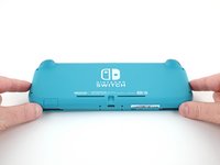
Usa un cacciavite tri-wing Y00 per rimuovere le quattro viti lunghe 6,3 mm che fissano il pannello posteriore.
-
-
-
Usa un cacciavite a croce JIS o quello PH 000 ufficiale di iFixit per rimuovere le seguenti viti di fissaggio del pannello posteriore:
-
Due viti lunghe 3,6 mm nella parte superiore del dispositivo
-
Due viti lunghe 3,6 mm nella parte inferiore del dispositivo
I accidentally stripped the back screw and now I can't open it. I removed all the other screws. What should I do?
-
-
-
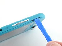
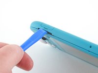
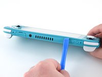
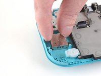
Inserisci uno strumento di apertura della griglia dell'altoparlante di sinistra, nella parte inferiore del dispositivo.
-
Torci lo strumento di apertura per sganciare le clip che bloccano il pannello posteriore.
-
-
-
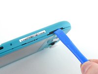
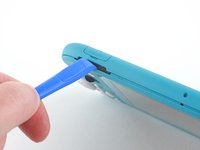
Fai scorrere l'attrezzo di apertura attorno al bordo inferiore sinistro per sganciare le clip sul lato sinistro del dispositivo.
-
-
-
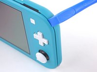
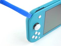
Inserisci uno strumento di apertura della griglia dell'altoparlante di sinistra, nella parte inferiore del dispositivo.
-
Torci l'attrezzo per sganciare le clip che bloccano il pannello posteriore.
-
-
-
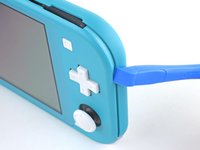
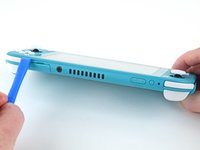
Fai scorrere lo strumento di apertura attorno all'angolo inferiore destro e usalo come leva per liberare le clip sul lato destro del dispositivo.
-
-
-
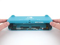
Solleva il bordo inferiore del pannello, aprendolo come un libro.
-
Rimuovi il pannello posteriore.
-
-
-
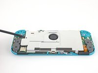
Usa un cacciavite a croce JIS 000 o quello PH 000 ufficiale di iFixit per rimuovere le seguenti quattro viti:
-
Tre viti lunghe 3,1 mm
-
Una vite lunga 4,5 mm
There are four screws instead of three mentioned
With how easy it seems to be to do serious damage with the next few steps, I figured I'd say that realistically you can skip steps 9-13 when doing this repair. While they provide a bit of extra security by disconnecting the battery, the left stick is completely accessible and replaceable without touching the heat shield or anything underneath (And steps 17 and 18 disconnect power from the daughter board regardless).
i stripped a &&^&^$^ screw
Well I actually removed the screw right next to the 4.5 screw. I did not realize it till my son showed me why the plate wouldn't release. Ha ha, it's funny now but yeah not a big deal. I could have bent it badly assuming I took all screws out though. For anyone reading this before going in. 👍
-
-
-
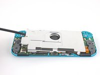
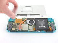
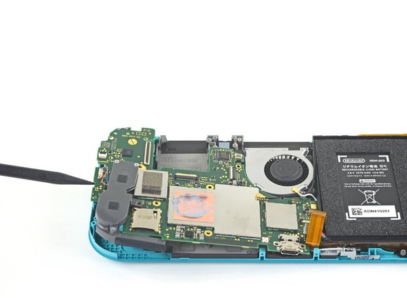
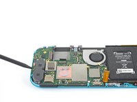
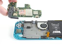
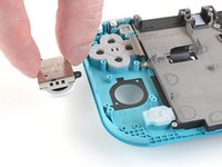
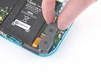
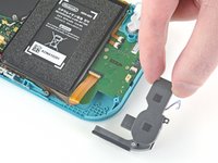
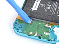
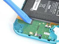
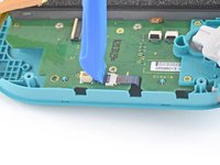
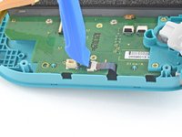
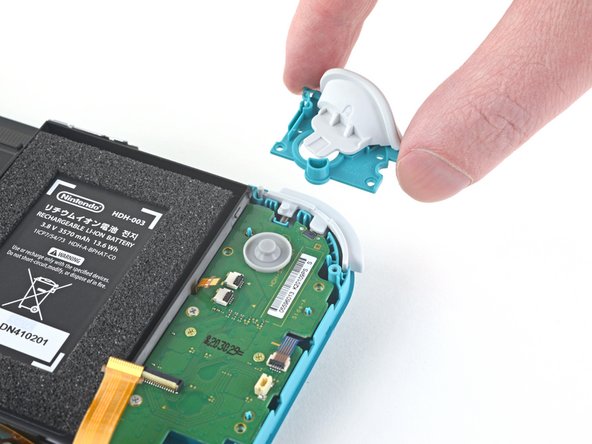
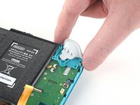
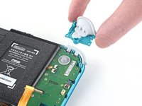
Usa uno spudger o le dita per sollevare la piastra di schermatura e staccarla dal dispositivo.
-
Rimuovi la piastra di schermatura.
What type of Thermal Paste would you guys recommend? I clicked on the picture but nothing.
Personnaly i use some Mx-6 from Artic, really good quality/price, never have to complain.
Nothing -
-
-
-
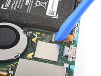
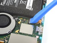
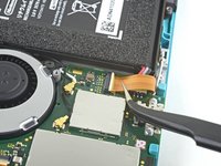
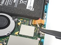
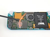
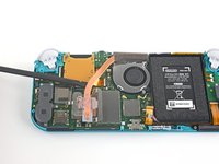
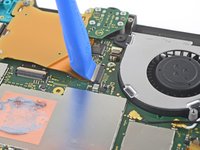
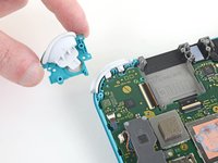
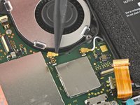
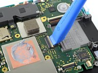
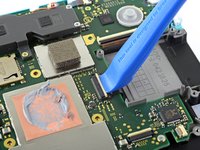
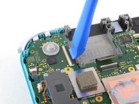
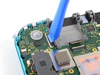
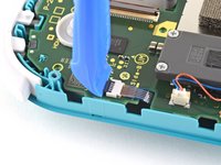
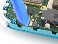
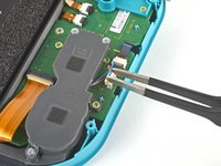
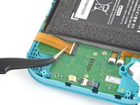
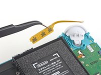
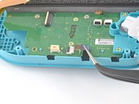
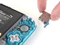
Usa uno strumento di apertura o un'unghia per ruotare la piccola aletta incernierata del connettore ZIF del cavo di interconnessione sulla scheda madre.
The clip broke off when trying to remove this cable. Audio only works through headphones and the display now won’t turn on after the clip broke. Does anyone know where I could get a clip or how I could fix it without it?
Mi è successa la stessa cosa è non so come ripararla! Chissà se c’è un modo!
-
-
-
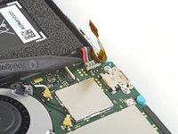
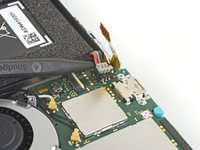
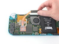
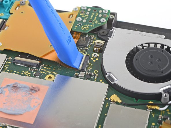
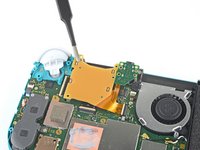
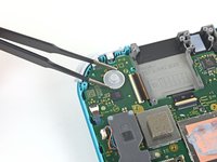
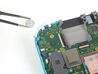
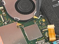
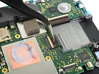
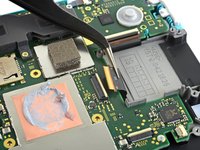
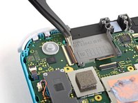
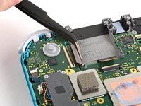
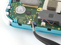
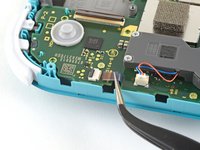
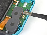
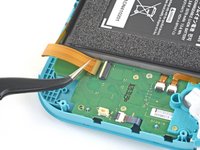
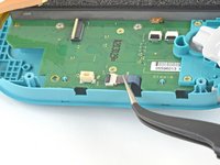
Usa delle pinzette per far scorrere fuori dal suo connettore e quindi scollegare il cavo di interconnessione sulla scheda madre.
I turned the unit off beforehand, I used tweezers just like the instructions said (ifixit branded) , my device sparked and now it won’t turn back on
The flap came off is it important or is there a way t fix it?
We're you able to get it working without the white flap? My screen is not working after putting it back together and i noticed this white flap was falling off
Did you get it working without the white flap? Everything on the switch works fine except for audio going through headphones and the display not turning on.
do not use metal sharp pointed tweezers! you will rip your ribbon cable. Use the inside of a Bic type pen or something else dull and plastic to pull the cable away by putting the pen part where the first bend is.
Maybe tape the Tweezers or smear some hot glue on them to insulate them to save you time and money.
Maybe put all the Warnings at the start of the guide as well. We fix it geeks tend to get excited when fixing things 😁
-
-
-
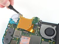
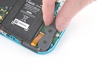
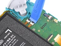
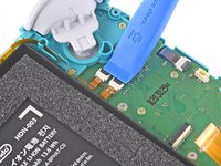
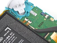
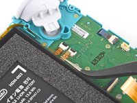
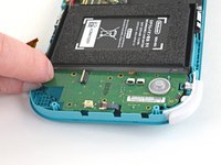
Usa l'estremità punta di uno spudger per sollevare il connettore della batteria estraendolo dal suo zoccolo sulla scheda madre.
Caution the connector may not be properly soldered onto the motherboard. For me it snapped off the pins and now have to find a place to get that fixed if even possible. may have bricked it.
Yup, broke the connector right off the motherboard. Thanks, ifixit -_-
I backed out when I reached this point. I couldn't risk damaging it. Do u just need to pull it up? Did you mean that it might have been soldered shut below?
You should just need to pull straight up, but make sure you’re pulling on the wires or the gray plug—do not pull on the black socket or it can snap off of the motherboard.
With how easy it seems to be to do serious damage at this point, I figured I'd say that realistically you can skip steps 9-13 when doing this repair. While they provide a bit of extra security by disconnecting the battery, the left stick is completely accessible and replaceable without touching the heat shield or anything underneath (And steps 17 and 18 disconnect power from the daughter board regardless).
just broke my connector... ifixit PLEASE put a warning on how fragile the solder on this connector is.
Note for this step, you do not need to apply a lot of force. I used two tools here: small screwdriver to hold down the black base, and one side of fine-tipped tweezers to get under all 3 wires. Gently, push down on the tweezers to push the wires upwards, which should force the gray connector up and off the base. It did not take a lot of force. Take your time and it will be fine. Again, like others have said, do NOT pull or pry up the black base.
-
-
-
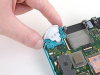
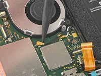
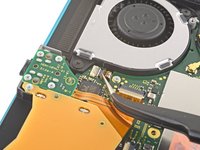
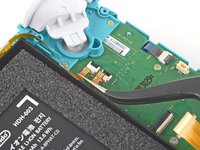
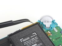
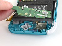
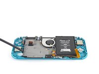
Usa la parte piatta di uno spudger per rimuovere delicatamente la schiuma adesiva sulla ventola.
When reassembling, the foam may fold down between the fan and heatsink, blocking airflow. Gently lift the foam back up on top of the fan. The adhesive film should hold the foam together.
Is removing the heat sink absolutely necessary?
It’s not necessary, but it makes it much easier to remove and replace the game card reader, since the heat sink partially covers the connector.
Not really…….. I never remove it. It slides out quite easily once disconnected.
-
-
-
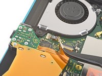
Usa un cacciavite a croce JIS 000 o quello PH 000 ufficiale di iFixit per svitare le tre viti da 3 mm che fissano il dissipatore alla scheda madre.
Non le tre ventole ma le tre viti
Grazie per avercelo segnalato! Ho apportato la modifica. iFixit è una wiki, quindi ogni utente può modificare le pagine: se trovi altri errori in futuro, sentiti libero di fare la modifica tu stesso!
-
-
-
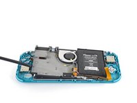
Usa uno spudger per sollevare il dissipatore dalla scheda madre e rimuoverlo.
16.5 remove cartridge / headphones jack……….
My kit did not come with thermal paste..
-
-
-
Usa un plettro o un'unghia per sganciare l'aletta di bloccaggio incernierata del connettore ZIF del cavo del lettore di schede.
-
-
-
Usa un cacciavite a croce JIS 000 o quello PH 000 ufficiale di iFixit per svitare le due viti da 4,5 mm che fissano il gruppo del grilletto destro alla scheda madre.
I think a whole step to remove the game card reader and speaker jack was skipped here…
yes, just found that sadly these comments do not show unless we click on the , which is unhelpful
also, you need to remove the left trigger button
-
-
-
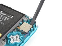
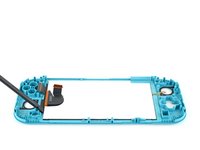
Usa la punta di uno spudger per far leva sul cavo nero dell'antenna e sollevarlo dalla sua presa sulla scheda madre
-
Ripeti la stessa procedura per il cavo di antenna bianco.
-
-
-
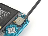
Usa un plettro o un'unghia per sganciare la piccola linguetta di bloccaggio incernierata del connettore ZIF della ventola.
-
-
-
Usa un paio di pinzette per sfilare il cavo dell'antenna dalla sua presa sulla scheda madre.
There’s a step missing after this to remove the screws that hold the orange game cartridge slot. Those 7 screws have to be undone and the ribbon unclipped first before moving on to the next step.
Good Looking out!
-
-
-
Usa un plettro o un'unghia per sganciare la piccola linguetta di bloccaggio incernierata del connettore ZIF del cavo dello schermo.
skipped a step or two about removing the golden piece in the photo above, and the other little board
If I broke the clasp on the ZIF connector can I elec tape it down?
What did you do to fix it if the ZIF connector broke?? Mine did too and I worry that is why the screen won’t turn on now
Missing the card reader + audio jack board removal. Just remove the 4 screws around the audio jack + 3 screws around the card reader and disconnect the ZIF connector from the motherboard.
-
-
-
-
Usa un plettro o un'unghia per sganciare la piccola linguetta di bloccaggio incernierata del connettore ZIF del cavo del digitizer.
-
-
-
Usa un plettro o un'unghia per sganciare la piccola linguetta di bloccaggio incernierata del connettore ZIF del cavo del joystick destro.
-
-
-
Usa un cacciavite a croce JIS 000 o quello PH 000 ufficiale di iFixit per svitare le seguenti sei viti che fissano la scheda madre:
-
Tre viti da 3,1 mm
-
Tre viti da 4,5 mm
how to get the c port off
When re-assembling, be sure the fan cable (step 25) is completely pulled through prior to tightening the screw that’s right next to it.
-
-
-
Usa un cacciavite a croce JIS 000 oppure un cacciavite PH 000 ufficiale di iFixit per svitare le due viti da 3,5 mm che fissano la levetta.
-
-
Attrezzo utilizzato in questo passaggio:Tweezers$4.99
-
Usa un paio di pinzette o le dita per tirare il connettore del cavo dello speaker di sinistra e rimuoverlo dalla sua presa sulla scheda figlia.
pulled from the connector, not the wires, and ended up ripping them off the connector anyways since it encountered tension from the other end (the gray chamber on the left)
consider doing step 15 before pulling the wire, just in case.
Why even disconnect this cable. Not worth the risk leave it connected to daughter board.
while doing this I ripped the pad on the circuit board off. Should i risk trying to repair it or should i just try to go without the speaker???
I also accidentally ripped off the connector, disabling the left speaker. However, that will not break any functionality of the switch. The right speaker works just fine on its own (just remember to turn the audio to mono in system settings) and I was successfully able to replace the joystick. Although the audio quality is a little bit depleted, you barely notice it if you turn up the volume a little, and I think being able to actually MOVE FORWARD in my games is a better plus than having louder, stereo, audio.
Went to pull the speaker connector and it pulled right off the motherboard. Would not come loose.
I'm gonna echo what others said here and suggest that you skip this step. After you complete Step 15, you can just move the speakers enough with your fingers to complete Step 26, which involves a screw half underneath it.
Regarding the ribbon cable in Step 17 & Step 18, you can honestly use your fingers if they're small enough. The ribbon cable is wide enough for you to press down on it a little and slide it out bit by bit.
Overall, this makes the disassembly and eventual reassembly process easier and lets you avoid running the risk of damaging or completely tearing out the wires, like I almost did.Removing the screw from 37 is enough to give you space to remove the board, I honestly think you shouldn't try to remove this connector.
Unfortunately, I had to reinstall multiple daughterboards on the same Switch Lite. I strongly recommend orienting your straight tweezers with ridges (like the ones in the picture) perpendicular to the device. Grab the plastic connector with the tip of the tweezers from the top. It makes inserting and removing this connection significantly easier.
-
-
-
Usa un plettro o un'unghia per sganciare l'aletta di bloccaggio del connettore ZIF del cavo di interconnessione.
-
-
-
Usa un paio di pinzette per sfilare il cavo di interconnessione dalla sua presa sulla scheda figlia.
-
-
-
Usa un plettro o un'unghia per sganciare le alette di bloccaggio dei connettori ZIF dei due cavi a nastro.
-
-
-
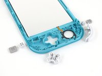
Usa un paio di pinzette o le dita per rimuovere i tasti del volume.
-
-
-
Usa un plettro o un'unghia per sganciare l'aletta di bloccaggio incernierata del connettore ZIF del cavo della levetta analogica sinistra.
-
-
-
Usa un paio di pinzette per sfilare il cavo della levetta analogica sinistra dalla sua presa sulla scheda figlia.
The connector for my left joystick broke. Is there a way to fix it?
How badly did it broke?
-
-
-
Usa un cacciavite a croce JIS 000 o quello PH 000 ufficiale di iFixit per svitare le due viti da 4,5 mm che tengono in posizione il grilletto sinistro.
-
-
-
Usa un cacciavite a croce JIS 000 o quello PH 000 ufficiale di iFixit per svitare le seguenti viti:
-
Due viti da 4,5 mm
-
Due viti da 6 mm
The two 4.5 mm screws were very difficult to remove here and ended up getting stripped. I CANNOT remove them, help!
-
-
-
Solleva la scheda figlia dal suo alloggiamento per rimuoverla.
Stop here if repairing Switch Lite for joycon drift. After removing daughter card you can see the bottom of the joystick. This thin metal actually bends during use causing bad connection of joystick. If you cut out a business card the same size as the joycon and put it on the bottom of the joystick it gives the metal enough backing to fix the issue. I used two layers with just a small bit of glue stick to adhere it. Put it all back together and you will find your issue is fixed.
That's great, but it's only Temporary.
You may as well put a New Stick in (preferably Hall Effect) after going through Hell to open the darn thing.
If you do choose the cardboard route, you may as well clean the innards of the Joystick, BUUUT, it's not easy getting the Joystick back together.
Daughterboard. That's a new one for me.
-
-
-
Usa un cacciavite a croce JIS 000 o quello PH 000 ufficiale di iFixit per svitare le 2 viti da 3,5 mm che tengono in posizione la levetta analogica.
-
-
-
Usa l'estremità piatta di uno spudger per sollevare la levetta dal suo vano.
-
Usando le dita, rimuovi la levetta dalla console.
During reassembly when putting the screws back in, slowly turn them CCW until you feel it drop into its thread. You will never crossthread them by doing this.
-
-
-
Usa un cacciavite a croce JIS 000 o quello PH 000 ufficiale di iFixit per svitare le viti seguenti:
-
tre viti da 2,5 mm
-
una vite da 6 mm
-
-
-
A questo punto, rimuovi tutti i tasti se non lo hai già fatto, per evitare che cadano e vadano persi.
-
-
-
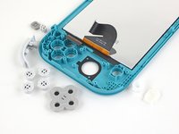
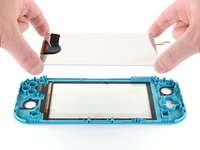
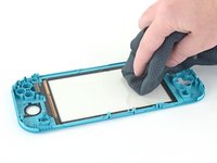
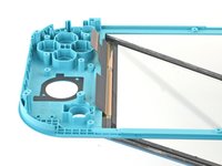
Scalda un iOpener e appoggialo sul retro dello schermo lungo il bordo superiore per 2 minuti per ammorbidire l'adesivo.
-
-
-
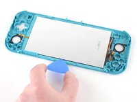
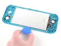
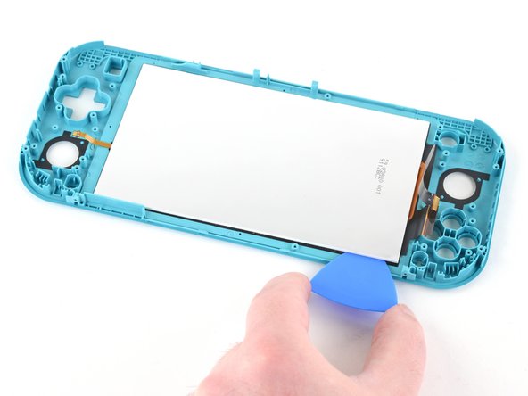
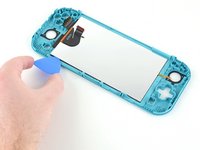
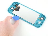
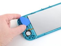
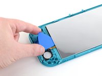
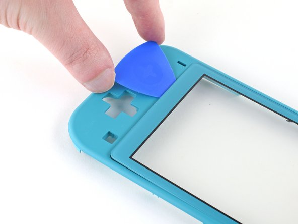
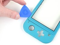
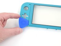
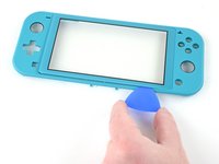
Applica un iOpener scaldato sul lato anteriore del digitalizzatore lungo il bordo sinistro per 2 minuti.
-
-
-
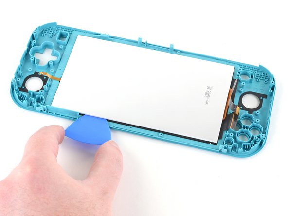
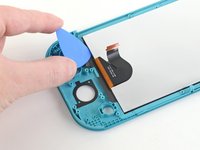
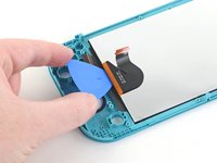
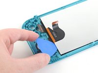
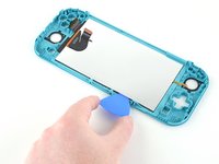
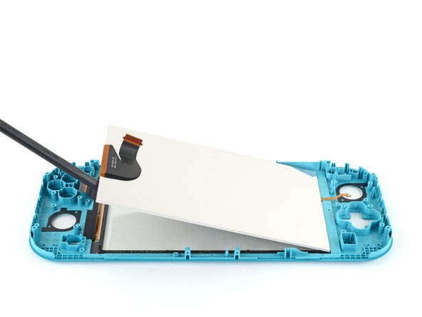
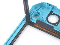
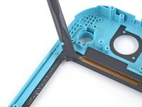
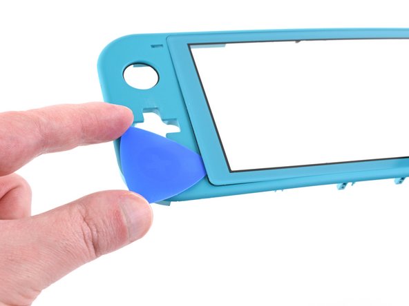
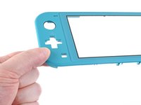
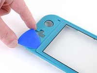
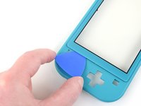
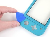
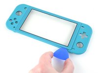
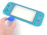
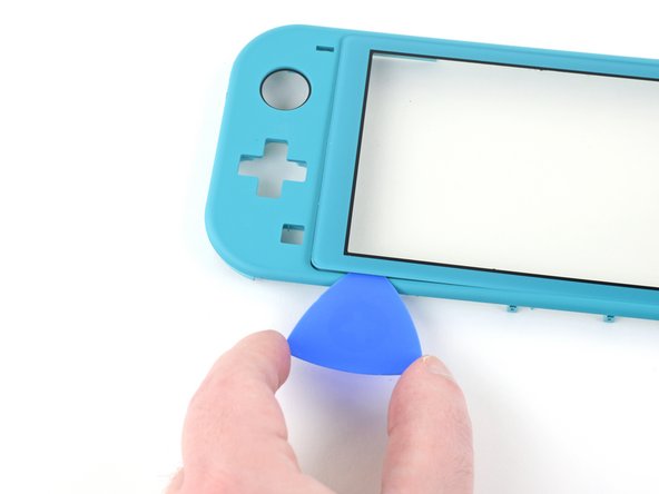
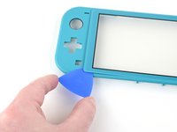
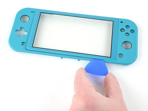
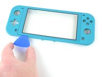
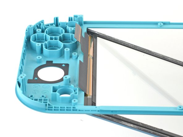
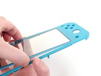
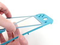
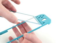
Solleva il bordo destro del digitizer dal telaio fino ad un angolo di circa 45° per rimuoverlo.
-


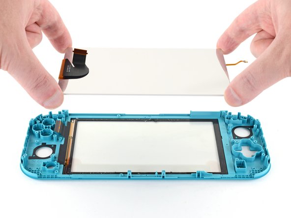


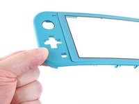


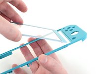
Per riassemblare il tuo dispositivo, segui questa guida al contrario.
Porta i tuoi rifiuti elettronici a un Riciclatore certificato R2 o e-Stewards.
La riparazione non è andata come previsto? Prova la comunità Risposte Nintendo Switch Lite per aiuto.
Per riassemblare il tuo dispositivo, segui questa guida al contrario.
Porta i tuoi rifiuti elettronici a un Riciclatore certificato R2 o e-Stewards.
La riparazione non è andata come previsto? Prova la comunità Risposte Nintendo Switch Lite per aiuto.
Annulla: non ho completato questa guida.
Altre 19 persone hanno completato questa guida.
Un ringraziamento speciale a questi traduttori:
100%


Questi traduttori ci stanno aiutando ad aggiustare il mondo! Vuoi partecipare?
Inizia a tradurre ›

4 Commenti
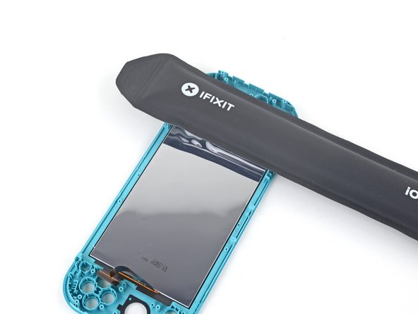
Great guide, but quick tip when removing the screen. There are two pieces of the screen sandwiched together and when I took mine apart, these two pieces came unstuck and ruined the screen itself. The digitizer was fine, but the LCD came apart. So make sure the opening pick gets under both of these parts rather than just the reflective back.
I bought this Switch Lite with a broken LCD to repair and sell, so the screen was already blown out, but I had the same issue. The LCD was still connected to the digitizer and it actually peeled the LCD apart. As I said earlier, the LCD was already broke so it wasn’t a big issue, but I would of been fairly angry if it hadn’t of been.
it looks like it might be possible to do steps 1 - 10, then step 28, then steps 66 onwards, and reverse to reassemble, the guide isn’t clear why it would be required to do a full tear down, is there something that would make this method not work or more likely to cause further damage, if I’m just switching out the digitizer, pun intended.. :) ?
Were I to guess, I would say that the full teardown guide is meant to apply to any, and all, scenarios, regardless of any unmentioned issues that a user may have.
Another possibility is that if a user has a damaged digitizer from a drop, or other type of impact(s); then by performing a full teardown, they may discover other elements in need of repair.
All my screws got stripped any ideas on how to remove?
Almost A Mammal - Replica
A Y0 screwdriver seemed to work better for me.
Tommy Morrill - Replica
What type of screw driver do I use to un screw the screws and which way
Luca Capito - Replica
Y 0.6 was all I had but it seemed to fit perfectly
Trevor - Replica
Like really snug? I've gotten away with using Drivers either bigger or smaller but I hate doing it. But if 0.6 is the exact size I need, then I'll get that. I don't wanna strip my client's Switch Lite's screws.
Vincent Valodze -