
iMac Intel 21.5" EMC 2308 CPU Replacement

Introduzione
Vai al passo 1Use this guide to upgrade your CPU.


-
-
Loosen the three Phillips screws securing the access door to the bottom edge of your iMac.
-
Remove the access door from your iMac.
-
-
Attrezzo utilizzato in questo passaggio:Heavy-Duty Suction Cups (Pair)$14.95
-
Stick a suction cup near each of the two top corners of the glass panel.
-
If your suction cups refuse to stick, try cleaning both the glass panel and the suction cup with a mild solvent.
Another comment on DATA & LCD Temp. Sensor cables: I had to remove the vertical sync, and the backlight cable, however, if you have an assistant or/can carefully rotate the screen clockwise/and then have it held up about 5" to 6" at a slight angle, you do not need to remove LCD data cable or LCD thermal cable, however - IMPORTANT: you must have a second pair of hands/or way to securely prop up the LCD. Also, don't rotate too much, since then you will pull out LCD data cable, and it renders the whole exercise moot, or can damage the cable or connector.
You don't need suction cups. The screen, held by magnets, can simply be pried off using a very thin blade such as a screw driver and fingers.
That's a bad idea. using a metal tool to pry off glass is likely to end with an expensive broken front glass.
Suction cups are common. Find a couple and do it the safe way. I use some cheap ones that came with iPhone repair kit.
No need for suction cups, I just stuck my nails (short like guys usually have) between the top part of the screen and body, and it came off easily. I've never done it before, so it seems to be very easy.
Just completed the replacement of the optical drive with an SSD using an OWC Data Doubler kit. Attempted to remove the optical drive without disconnecting any cables but found it a bit fiddly to orient the screen for good access. I bit the bullet and disconnected them and found the process less daunting than I imagined. Reconnecting them was similarly straightforward if you're careful.
Tip: you can skip the step for removing the optical drive thermal sensor connector from the motherboard. Still need to remove the sensor from the optical drive but you can leave that hanging and reattach it to the SSD later.
I’ve just successfully installed a 1TB SSD in place of my optical drive thanks to the information here- thank you to everyone who has contributed!
3 comments- the procedure described here seems to vary between HD replacement and dual HD/optical drive replacement. This can be confusing at times.
Expect there to be minor differences between the layout described and what you find when you open up your iMac. There are also, surprisingly, differences between the HD enclosure description, and the article provided by ifixit.
I was able to replace the DVD/HD enclosure single-handedly without fully removing the LCD, or deconnecting any of the cables (steps 5-11). It’s a bit cramped, and fiddly, but I was not happy removing any of the cables despite watching videos, etc., since they all seemed to involve applying more force than I was comfortable with. A more detailed description of how to release them might have helped, but even here, there may be minor variations even within the 2389 model.
Good luck!
Fingernails are all you need to free the glass from its magnetic hold. If you don’t have them, slip something thin and plastic, like a spudger, at a top corner.
Minha dúvida é a seguinte: após o técnico trocar o HD do meu iMac de 21,5 polegadas, a câmera parou de funcionar. Seria por causa da troca do HD? Tem solução?
Creio que o cabo da camera não foi plugado ou deu mau contato… ou até danificado.
glecyo@gmail.com
I can’t get my glass to budge. I’m replacing a cracked one and now it’s about to shatter.
I know that I'm replying really late but I advise to use clear tape over any cracks so the cracks don't get bigger
Check for chips in the glass BEFORE you do this step. If there is a chip when you pull up with the suction cups you will wind up with a jagged mess. If you do have a chip I would advise covering the screen near the chip with clear tape of some kind before lifting out. Mine shattered right at the chip and the resulting glass dust cloud got all over. My solution was buying a new glass screen.
-
-
-
Gently lift the glass panel perpendicular to the face of the LCD enough to clear the steel mounting pins attached along the underside of the top edge of the glass panel.
-
Pull the glass panel away from the lower edge of the iMac and carefully set it aside.
What's the best product to clean the face of the LCD?
Microfiber Cloth
Try your best not touch it in the first place
Brian -
Wearing Nitrile or regular surgical gloves helps prevent finger prints if you accidentally touch the glass.
I use a Swiffer duster from above at the last moment before I let the magnets grab the glass cover. This has worked so well the last dozen or so times I’ve replaced a glass cover since I never have access to a “clean room” and don’t wear a “bunny suit”.
Also, more dust will shed from your skin if you’ve just taken a shower, so I like to finish these repairs in the morning before a shower.
-
-
-
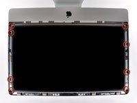
Remove the eight 8 mm T10 Torx screws securing the display to the outer case.
8 vis, pas 2
On reassembly, it is REALLY HARD to align those screws, because of the field of the strong magnets that hold the glass cover on. I'm sure there's a trick to it, but I'd love to know what it is for future reference.
A short piece of small gauge vinyl tubing that fits tightly over the head of the T-10 driver leaving an 8th of an inch or so in which to insert the screw to engage the head will hold the screw long enough to keep it away from the magnet and get it going in the hole.
I use non magnetic SS curved tip tweezers together with a magnetized #10 torx bit both to remove and reinstall the screws. You can magnetize and demagnetize the bit using the strong magnets on the LCD frame. Don't worry too much during removal, you can recover the screw. But loath the moment you drop the last screw during reassembly. For that reason, reinstall the screws near the magnets and hardest to get to first.
-
-
-
Slightly lift the top edge of the display out of the outer case.
When putting the display back I have resistance from the foam elements (on the top end where the iSight is) and have to press down really hard. Is that okay?
Well, stupid me put the 3.5" to 2.5" cage the wrong side up. ;)
-
-
-
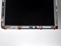
Pull the vertical sync ribbon cable out of its socket on the LED driver board near the top left corner of your iMac.
Reassembly of this part was the closest I came to disaster on this project. I tried inserting the connector a few times without success, and when I looked it it the leads, which are fragile, were all mangled. I smoothed them out by hand as best I could and and reinserted, very carefully this time. The trick is that the tip of the connector should be pointed somewhat upwards when reconnecting.
I was pretty sure that when I was done, I would reboot but have no display; but fortunately, everything worked.
So let’s say someone wanted to suck some of the dust off the back of the display before reassembly. Let’s just say that. Someone would likely suck this forsaken cable up into the vacuum tube then, wouldn’t they? They might. And if it were to oscillate in a rushing torrent of air, it might get munged? It might.
Here’s how you overcome such a disaster:
1) cut the end fresh, as close to the end as you can while cutting off any frayed end.
2) abrade the end gently, repeatedly, along the connector wire axis. I used emory paper. Your goal is to expose the copper conductors in the last 1/4” of the fragile evil wire.
3) Tape a small stiff cardstock to the back of the end of the connector. This is essential to press the connector wires into the connector.
4) Gently insert, taking special caution to not peel the copper off of the connector.
5) Tape that connector down deftly, without letting it move a millimeter and securing it for all time.
I just leave it connected. After disconnecting the other cables, there is enough slack to lay the display on its backside if you’re working on a flat surface.
I have replaced the hdd in this model about 8-10 times - I have never had to disconnect any cables other than the sata and temp sensor cables on the hdd. I just prop the lcd up with an egg carton (or something about 3 inches high that is soft and light) and access the hdd that way. The only thing I ever have trouble with are is putting the LCD screws back in around the magnets - but I have pretty much perfected that with a sissor/ tweezer tool.
Could you put up some photos of this procedure - egg carton etc…
The LCD screen is super soft on these since they rely on external glass for protection. Since LCD side will be facing down without disconnecting vsync, I'd lay it on a flat surface with soft fabric rather than putting the LCD on a rough surface like egg cartons.
Howard -
Any ideas where to replace this cable?
I followed Suzanne’s comment and also did not disconnect this cable (vertical sync ribbon cable) to avoid damage. I pivoted the screen about 110 degrees after the other cables where detached. On a flat surface, this is easily done and the cable is not tight. Image of my angle if I can drop a link. and cable in this position not in tension.
Where can I buy the replacement for this vertical sync replacement cable?
-
-
-
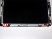
Rotate the display out of the outer case enough to disconnect the LED backlight power cable from the LED driver board.
I found it easier to very slightly lift the front edge of the black connector with a small spudger, then gently pulling away towards the bottom of the iMac. Pressing felt a little crude and didn’t work for me.
-
-
-
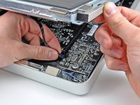
Squeeze the two display data cable connector arms together to unlock it from its socket on the logic board.
-
Pull the display data cable connector away from its socket on the logic board.
Aperte as duas exibição do conector do cabo de dados braços juntos para desbloqueá-lo de seu soquete na placa lógica.
Il vaut mieux déconnecter la partie du côté écran en premier (sous l'autocollant noir)
Je suis d’accord. C’est plus facile. Merci mon ami
Translation: It is better to disconnect the screen side first (under the black sticker)
ALWAYS ALWAYS ALWAYS REMOVE THIS CABLE!!! Even if you are "only in there for a minute" tearing the connector off the board is EXTREMELY easy.
-
-
-
Disconnect the LCD thermal sensor cable connector from its socket on the logic board.
This is important regarding the fan running full speed
Is there a way to test the power supply to see if it's dead?
Achtung! Dieser Stecker kann sehr fest sitzen, hier hilft ein guter Fingernagel um den Stecker abwechselnd rechts und links zu Hebeln
English translation of bluesoundsmusic comment: “Caution! This plug can be very tight, here a good fingernail helps to lever the plug alternately right and left”
-
-
-
Remove the following four screws securing the power supply to the outer case:
-
Two 22.2 mm fine-thread T10 Torx
-
One 25 mm coarse-thread T10 Torx
-
One 9 mm coarse-thread T10 Torx
fuuuuuuuck shiiiittt dammn that mf hurt like !&&* fucckken shocker here guys this macpos WILL KILL your ass be &&^&^$^ aware
I installed the power supply and nothing happened when I pushed the power on button, has this happened to someone else or should I also replace the power cable?
Okay, is the side with the soldier joints or the side with the capaciters the “face?”
Also, you need to destroy that little hook that keeps the big connector on unless you have three strong little hands. Don’t worry, it’s not going to fall off, you can still cut yourself trying to wiggle that thing off. Especially when you are holding the board by the edges to avoid the “face.”
I've taken out the logic board on a late 2009 iMac twice in the last two years, and in neither case did I need to remove the power supply. You can do the rest of the steps without removing the power supply, so I would suggest just making things simpler and leaving it in.
-
-
-
Carefully lift the power supply out of the outer case and rotate it to expose the cable lock as shown, minding the DC-Out cable still attaching it to the iMac.
-
Disconnect the DC-In cable by depressing the locking mechanism on the connector while you pull the connector away from its socket on the power supply.
-
Once the locking mechanism has cleared the socket, pull the DC-In connector away from the power supply.
I found my DC-In cable VERY difficult to detach. I depressed the locking mechanism, but still needed to use my iFixit Jimmy to carefully, gently, slowly work the cable connector (male) loose and away from the power supply (female).
-
-
-
Disconnect the AC-In cable by depressing the locking mechanism while pulling the connector away from its socket.
-
Remove the power supply from the outer case.
This was not easy to disconnect with one hand holding the power supply (being careful while holding just to be cautious against any possible electrical discharge). Note that the connector is not on power supply side but on AC-In cable side. Couldn't quite see well enough from photo shown, but hold on the AC-In side of cable connector (depressing the locking mechanism of the male side) and pull away from the Power Supply (female side) cable.
i’ve gotten away with not removing the PSU at all when removing the motherboard. havent had any issues
-
-
-
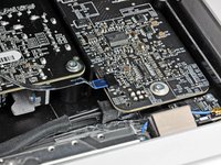
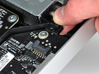
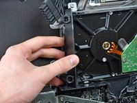
Pull the optical drive thermal sensor connector straight away from its socket on the logic board.
While you’re here, disconnect that SD reader cable and don’t forget to plug it back in on your way back through: it’s not mentioned elsewhere in this guide.
For me this cable was by the hard drive with a grey and a black wire labeled “ODD_TEMP”
-
-
-
-
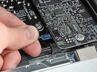
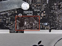
Use the flat end of a spudger to help disconnect the optical drive cable.
Be sure this cable doesn’t get stuck under the logic board during reassembly. Mine was under it, I was able to get it out but connecting it to the SuperDrive required a bit of force because my cable is so short.
-
-
-
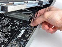
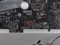
Remove the single 13 mm T10 Torx screw securing the optical drive fan to the outer case.
-
-
-
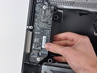
Pull the optical drive off the pins attached to the outer case.
-
-
-
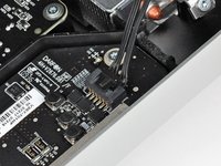
Pull the left and right speaker connectors toward the right side of the iMac to disconnect them from the logic board.
I added a small piece of tape to one of the cables and took a picture to remember where each of them go
I used a paint pen to draw a line across one of the sockets and its connector before removal
-
-
-
Disconnect the AirPort cable by lifting its connector off the socket on the logic board.
Lift this one directly up towards your cieling. I almost snagged this one off like it was the other cables.
-
-
-
Disconnect the following cables by pulling their connectors toward the top edge of the iMac:
-
Camera cable
-
Hard drive thermal sensor
-
Hard drive fan
-
Microphone
-
Disconnect the following cables by pulling their connectors toward the right edge of the iMac:
-
Ambient temperature sensor
-
Bluetooth cable
You might need a spudger to pull the wires out in order to pull ambient temperature sensor and Bluetooth cable out. For mine, the cables were tucked in so it was really difficult just pull out the wires.
The Bluetooth cable was refusing to disconnect. The cable goes under the logic board pulling the connector down, especially on my iMac it was very tight. What ultimately helped was sliding the flat end of the iFixit Halberd Spudger under the connector, lifting it slightly up. Then I was able to pull it out of the socket.
-
-
-
Disconnect the CPU fan and power button by pulling their connectors toward the left edge of the iMac.
-
-
-
Remove the following six screws securing the logic board to the outer case:
-
Three 25 mm T10 Torx
-
Two 21.5 mm T10 Torx
-
One 7 mm T10 Torx
These photos do not show this iMac's optional configuration that contains a discreet GPU. If a GPU card is present there is another Torx screw that must be removed that holds an additional heat sink to the upper right corner of the enclosure. Note that in this configuration, the optical drive fan has a different configuration with a plastic separator that points towards the top of the iMac. This looks to serve as channel for airflow and is noteworthy because it makes the optical drive's SATA connector much more difficult to remove and quite difficult (for me anyway) to reassemble as it is a very tight fit!
I made it to this step, then carefully removed dust from the back part, not touching any components, then used compressed air to get dust out since getting the whole logic board was a challenge, assembled and when I turn it on it loads normally, white screen with the logo, but then the screen goes black, and then the fans start running at the actual speed (I used SMC fan control) I had before I unplugged it to clean it, what could have happened? thank you =(
-
-
-
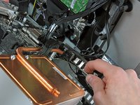
Carefully remove the aluminum tape attaching the GPU heat sink to the outer case.
OMG!
I cannot believe it!
Only by attaching one side of the golden GPU sionk with aluminum tape on the case, is it possible to well handle the thermal dissipation from the GPU
Whoops, definitely tears easily. I tore it at two spots. At reassembly I was able to get it to adhere to the case nonetheless by rubbing along the aluminium tape using my finger nail.
-
-
Be sure you have REMOVED YOUR RAM MEMORY before trying to wiggle out the logic board!
Thank you! I don’t understand why it’s not mentioned in the guide
-
-
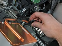
Carefully pull the logic board slightly away from the outer case.
-
While holding the board away from the outer case, rotate the board back and forth while lifting up to release it from the outer case.
During reassembly make sure all I/O connectors are above the logic board and not under it! I also connected three USB drives to align the logic board.
-
-
Attrezzo utilizzato in questo passaggio:Tweezers$4.99
-
Use a pair of tweezers to lift the heat sink thermal sensor connector straight up out of its socket on the logic board.
-
-
-
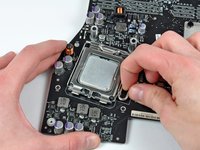
Carefully pull the CPU retaining bar away from the CPU socket.
-
Rotate the bar toward the center of the logic board.
-


To reassemble your device, follow these instructions in reverse order.
To reassemble your device, follow these instructions in reverse order.
Annulla: non ho completato questa guida.
Altre 32 persone hanno completato questa guida.

19 Commenti
Hello I fixit.!
Hello a lot of congrats! for your site! is very very helpfully for Mac Users
so. i have a question please if you want to help me.!
i have an i mac 21,5 late2009
3,06ghz intel core 2 duo
i have an idea to change the processor to. intel core i5 3,3 Ghz core
can be compatible . on main board .
thanks a lot for your time
These 21.5" (and 27") iMacs came with only either Core 2 Duo E7600 (3.06Ghz, 2 core, 65W TDP, LGA 775) or Core 2 Duo E8600 (3.33GHz, 2 core, 65W TDP, LGA 775), which are incompatible with any Core i5 as there are no Core i5's that were available on the LGA 775 socket these systems.
You might be able to upgrade to a Core 2 Quad Q9505S or Q9550S (2.83GHz, 4 core, 65W TDP LGA 775) which would provide 2 extra cores than the E7600/E8600 and work in the same socket but drop the max clocks to stay at the same 65W TDP power limit.
I installed a Q6700 Core 2 Quad into my late 2009 Core 2 Duo iMac.
Sadly it is not working, only recognize 2 Cores instead 4 under Windows 7.
Booting in the lates Mac OS, it gives up Kernel panic.
Any advise?
The Core 2 Quad Q6700 is a 105W TDP processor and the 21.5" & 27" iMacs running the Core 2 Duo E7600/E8600 only support 65W TDP LGA 775 Core 2 processors. If you wish to upgrade from the Core 2 Duo E7600/E8600 to a Core 2 Quad in these systems; I would recommend wither the Q9505S or Q9550S - specifically the "S" on there as those are the 65W TDP versions of the 105W TDP Q9505 and Q9550.
Windows is only allowing 2 of the 4 cores of that Q6700 to run to fit within the TDP of the system (particularly by regulating how much power the CPU can draw), and MacOS is panicking as it doesn't know how to handle the 105W the Q6700 is asking for on a 65W system.
Hello,
I'd like to upgrade the Core 2 Duo 3.06 CPU of my iMac 10,1 21.5". I already done the same operation in a white Core Duo iMac, being able to install the unsupported OS X 10.7. I'd like to do the same on the 10,1 but what CPU can I install? It seems that the i3, i5 or i7 are phisically different, am I right? And the user Tim report in being unable to make it work with a Core 2 Quad. So... what are the possibilities? Thanks!
hello, im planing to upgrade to i7 or i5 S type cpu with only 65w tdp(same tdp as my core 2 duo) , so im thinking, if the logic board supports those, and will i be able to even start up my mac...just want to see more cores in my computer...
The 21.5" & 27" iMac's running Core 2 Duo E7600/E8600 are only compatible with other 65W TDP Core 2 processors such as the Core 2 Quad Q9505S and Q9550S on Socket LGA 775, as there have been no official LGA 775 Core i3/i5/i7 processors from Intel.
dear ifitxit guys.. i have a 27" imac 306 dual. has anyone one tried to your knowledge using the q9550s quad core with any success. this could be an "ultimate" upgrade bringing it very close in speed to the i7s. seeing how th q9550s is running around 100 dollars on ebay it could make a very affordable upgrade. please let us know if you have any info on this. thanks
It is impossible to replace a socket 775 cpu with an i3 , i5, i7 series , regardless the generation . They fit into a completely different socket . So , if you are lucky , maybe a Q6600 will work , as it's socket 775 core 2 quad cpu , 1066 mhz . Or a faster core 2 duo . Nothing else .
Core 2 Quad Q6600 and other non-S Core 2 Quad processors are non-viable upgrade options for the 21.5" & 27" iMacs Core 2 Duo E7600/E8600, as the systems are built for 65W TDP LGA 775 processors, and the only 65W TDP Core 2 Quad processors are the Q8200S (2.33GHz), Q8400S /Q9400S (2.66GHz) and Q9505S/9550S (2.83GHz).
On reassembly, before you bolt down the logic board, make sure all the cables that plug into it are routed correctly. Better yet—plug them. As well, make sure the HDD/SSD’s SATA cable is routed correctly or else the mainboard won’t sit flush, which will be noticeable when you try to remount the optical drive/gpu fan.
Very straightforward and well documented guide. I have to say that Apple computers are very cumbersome to handle (my expertise are high end PC computers). My wife likes IMacs, so I have to take care of her A1311. Hats off to a very good guide.
I have a question about the possibility of repairing the video card. Can it be done or is it surface mounted. I ask because the video on the IMac is scrambled and I do not know how to fix it……
Thanks
Is it the 9400 nvidia onboard or the extra ATI4670 video card?
Alex Vou -
Nice processus
Thanks for this tutorial, I did remplace the 3,06 GHz Core 2 Duo with a 3,33 Core 2 Duo on mid 2020. At my first attempt, the CPU wasn't recognized by the system, (I still don't know why, the iMac was up to date) so I decided to put back the old CPU. A couple of month later, I decided to do a second try, and then, TADA, it’s working!! One of the advantage of this CPU is that it support an higher Ram frequency from 1066 MHz to 1333MHz (CPU speed bus is quicker on the 3,33GHz core 2 Duo).
hello Pierre-Alexandre Porchet, how good you wrote this message, because the same thing happened to me. a "panic_cpu" appears, at the beginning the imac started normal, but it got stuck, then it did about 10 reboots with the indicated error. Now I think about going back and casting the old "3.06MHz" cpu. My question is the following, what do you think, did it make a difference on the second try, was it a different connection, or was it just a matter of imac software logs?
Boa tarde Amigo! qual a sugestão para atualizar Imac ano 2009 core 2 duo 3.06Ghz para o 3.33 Ghz E8600??
como posso fazer esse processo ?
Buy the E8600 on eBay, AliExpress or Jawa, follow the guide to gain access to the iMac's CPU, replace it, apply new thermal compound, and then reassemble the system.
It might take a few reboot cycles to retrain the system to accept the E8600 as other users have found.
In order for the logic board to come out cleanly, one should remove the RAM at the end of this step.
kevmacmills - Replica
Definitely! The author should make this as a step in the description (because not everyone reads Comments)
finnik2d - Replica
Just did this procedure and the RAM must absolutely come out for the logic board to come free later.
matt - Replica