Hi,
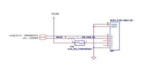
Here’s an image taken from the Lenovo T440s motherboard schematic which shows the connector wiring to the LED and power button card. (I think).
Even though it shows 8 wires to the connector but only 6 are in use through to the card so perhaps they are the 6 that you mentioned.
I suspect that the power switch is between wires 6 & 1 and the LED is between wires 3 & 5 but as the LED is a diode the cathode would need to be on 5.
I may be wrong about all this but this is the closest that I can find that deals with the power and LED button board in the schematics. You may find it elsewhere in the schematics in case I missed it.
I’m not sure if +ve and -ve are important for the switch, but it would be necessary for the LED light.
Perhaps you could use an Ohmmeter and check the old LED/power button board when it is disconnected from the motherboard and work it out that way.
With the old button board disconnected from the motherboard place the meter’s test leads across the board cable connector pins 6 & 1 and check if the Ohmmeter tests short circuit (or resistive continuity) every time the switch is operated. The same with the LED light. If you connect the Ohmmeter across pins 3 & 5 you should have a low resistance in one direction and if you reverse the test leads a high resistance in the other direction i.e. a diode test.
(click on image to enlarge for better viewing)
Hopefully this is of some help.
Questa risposta è stata utile?
Votato
Annulla
Punteggio
2
Annulla
Scorri questo thread per trovare il posto appropriato per questo commento. Quindi, fai clic su "Allega commento a questo post" per spostarlo.