
Voluas VL001 Speaker Replacement

Introduzione
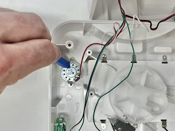
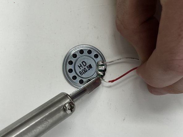
Vai al passo 1If your Voluas VL001 pet feeder audio recording is distorted or is not playing when your kibble is dispensed, this has to do with your speaker. The speaker plays a voice recording of your voice so your pet recognizes when it is time to eat.
This replacement requires special skills like wire stripping and soldering.
Cosa ti serve
Strumenti


Mostra di più…
-
-
Remove the lid to the storage tank by using the latch and lifting off.
-
Grab the food storage tank on both sides. Depress the tabs that say "Push" on them and lift the tank off.
-
-
-
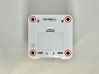
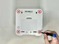
Place your pet feeder upside down.
-
Squeeze the lock and remove the battery cover.
-
Remove the three 1.5V D alkaline batteries.
-
-
-
Insert a metal spudger under the adhesive part of each rubber foot.
-
Pry the foot off.
-
-
-
-
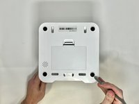
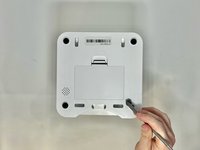
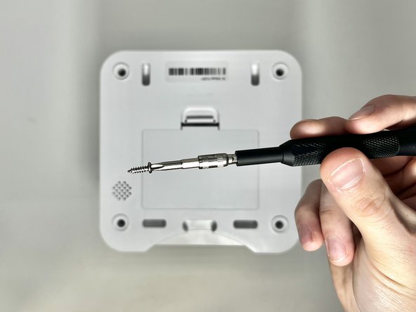
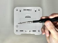
Using a Phillips #2 screwdriver, remove the six 11.2 mm screws that hold the motor housing on to the device.
-
Remove the motor assembly and set it to the side.
-
-
-
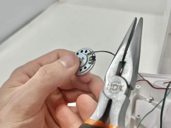
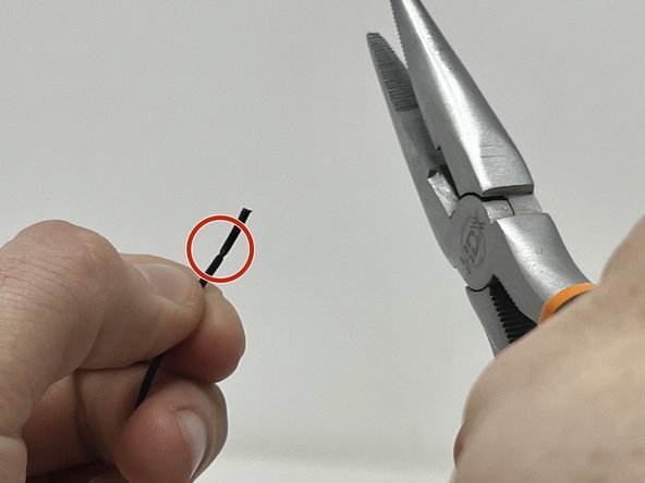
Using your wire strippers/pliers, gently crimp the plastic insulation on the wire. Do this several times around the wire to make sure that you can pull it off.
-
You will want to see a score line in the insulation all around the wire like this.
-
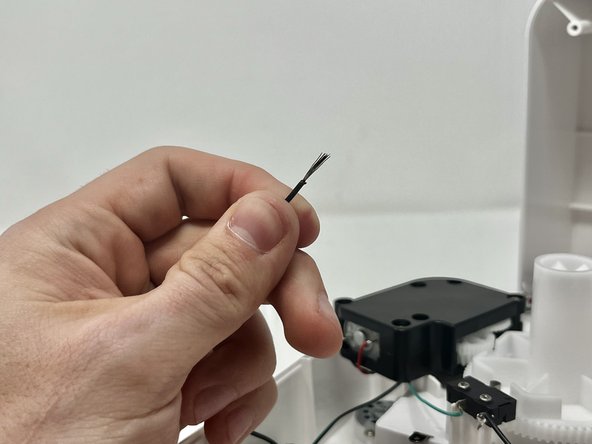
Pull the end of the insulation off, exposing the wire.
-


To reassemble your device, follow these instructions in reverse order.
To reassemble your device, follow these instructions in reverse order.

Team

Utah Tech University, Team 1-3, McMurrin Spring 2024 Membro di Utah Tech University, Team 1-3, McMurrin Spring 2024
UTAHTECH-MCMURRIN-S24S1G3
2 Membri
10 Guide realizzate