
Sostituzione Scheda Logica Mac mini Model A1176

Introduzione
Vai al passo 1Questa guida ti mostrerà come sostituire la scheda logica.
Cosa ti serve


-
-
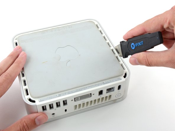
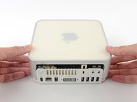
Spegni il tuo Mac mini, scollega tutti i cavi e capovolgilo.
-
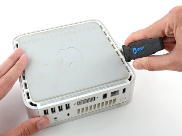
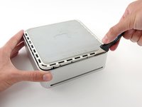
Inserisci il Jimmy nella fessura tra la copertura superiore in alluminio e la copertura inferiore in plastica.
-
Il Jimmy dovrebbe fermarsi a circa 1 cm di profondità.
-
-
-
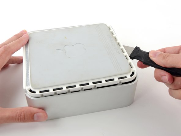
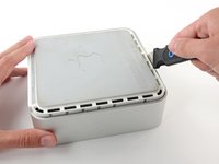
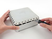
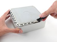
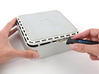
Piega delicatamente il Jimmy verso l'esterno per allargare un po' la fessura e sollevare leggermente la copertura inferiore.
Patience is your best friend.
Do not insert “jimmy in too far. Marking a line from tip upwards on the tool will prevent too far insertion, possibly breaking tabs or damaging internal components.
To prevent the cover closing back up, small strips of matchbook cover (os equivalent) can be inserted about half inch hold prevent closure.
I think it needs to be made more clear that what you want to be doing is applying upward pressure on the back I/O panel with your HAND while pressing the clips with the jimmy, sort of like tensioning a lock and then setting individual tumblers. (Yeah, I watch LockPickingLawyer.)
The pictures appear to show trying to lift the lower housing using the jimmy, similar to how I've seen people doing things like prying with a putty knife or screwdriver... and that plastic is only going to get more brittle over time.
If you apply the upward pressure with your hand via the back panel and then work your way around the outside edge clip-by-clip, then it's much easier to be gentle with the jimmy because your only goal is to press on each clip enough to release it. All the rest of the force comes from, say, a finger hooked into the edge of the Ethernet port and a thumb pressing on the edge of the top cover.
-
-
-
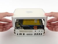
Capovolgi nuovamente il Mac mini e solleva la parte superiore della copertura da quella inferiore.
-
-
-
Premere leggermente le due linguette di fissaggio l'una verso l'altra e sollevare l'antenna AirPort dal proprio alloggiamento.
-
-
-
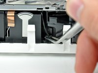
Utilizzare la punta di un inseritore per sollevare leggermente il lato sinistro del bloccacavo ZIF dal rispettivo connettore femmina.
Good catch of the incomplete unlocking instructions. ;P
Hmmm... what if I didn't read this before and I removed the cable and the lock sort of broke?... what would happen... would I experience problems? I can still put the cable back in place and push the lock back down with the spudger.
Same. I totally removed the lock , the edges are busted and won't stay in place, How can I get the cable to stay? what's the fix?
Suzanne -
Dan O & Suzanne, hold the cable in the socket and put a dab of hot glue on both sides, It's non-conductive and should hold...worked for me.
does any one know, where to get the connector from zhe ZIF Cable?
someone, that preowned my mac broke the holder!
Julian, did you ever find where to get a replacement lock for the Zip Cable. Mine is also broken..
Suzanne -
This is not my first memory replacement in a Mini and I got over-confident and stupidly fully removed the audio cable ZIF lock and assumed I had broken something. But, now that I have read this guide more carefully, I am not sure. I sure would love to hear some detailed instructions for putting a ZIF lock back on.
Is it possible that I have removed it without having broken it? If I have broken it, do I have to buy a new cable? Just a new ZIF lock? A new audio board? This is a 2.0 GHz A1176.
Thanks!
Michael, Mine seems to be broken. I bought & tried the Kapton Tape that was suggested & still no sound.
Suzanne -
-
-
-
-
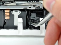
Sollevare il cavo piatto della scheda audio dal connettore femmina.
As an option to avoid potential damage when disconnecting the cable from the ZIF socket and clip, it is possible to unscrew the audio board and remove it along with the internal frame.
-
-
-
Mediante un paio di pinzette, sollevare connettore del cavo del sensore termico del disco rigido dal connettore femmina sulla scheda logica.
I've had to remove a few of these connectors on iBooks and other small Apple devices ... I've found that, with careful and gentle pressure (working first one side and then the other) using a small flat-headed jeweller's screwdriver is best.
I agree Mike.
-
-
-
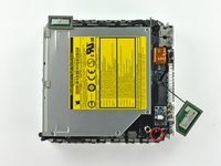
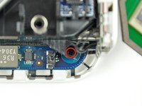
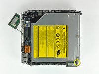
Rimuovere la vite con testa a croce dal telaio interno, in prossimità dell'antenna Bluetooth.
Before removing any of these screws, there is another step needed which is not here:
On the front of the optical drive, right side as you look at the slot-load, is a small blue board attached by a single black screw. This needs to be removed before the optical drive can be taken out.
-
-
-
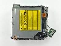
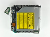
Rimuovere la vite con testa a croce accanto alle porte audio, che fissa il telaio interno al case inferiore.
-
-
-
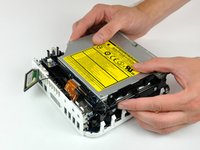
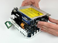
Sollevare delicatamente il telaio interno dall'alloggiamento inferiore, facendo attenzione a non incastrare il cavo dell'antenna AirPort o altri cavi.
At this point be careful that you don't pull out the Airport antenna ... but if you do, just check that it is back before re-assembling.
During re-assembly, the internal frame has to go in at an angle ... the back of the optical drive goes in first.
This means that you can seat the fan cover correctly, but more importantly, there is an interconnect board on the back of the optical drive that must be firmly pushed back into its housing on the logic board.
If, like me, you pull the wire on the airport antenna free, it snaps back into place easily. The connector is on the extra card screwed to the motherboard that looks like it has a phone battery embedded in it. The connector is at the top of the 'battery'. This accessory card is the wifi card, so it makes sense that the antenna plugs onto this.
-
-
Attrezzo utilizzato in questo passaggio:Tweezers$4.99
-
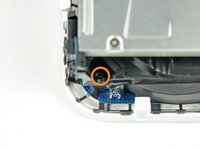
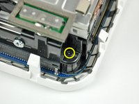
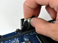
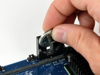
Afferra saldamente il connettore del cavo del pulsante di accensione con una pinzetta e sollevalo verticalmente dalla scheda logica.
-
-
-
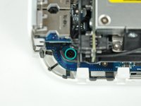
Rimuovi la vite Torx T10 che fissa la scheda logica al telaio inferiore.
-
-
-
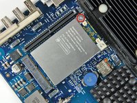
Solleva delicatamente la parte finale libera della scheda logica e muovi leggermente la scheda mentre la tiri via dalle porte I/O.
Hi, when re-assembling, if you find resistance to the board sliding right up to the rear panel make sure that the spring finger on the casing goes over the power connector not inside it. It fits much better that way!
-
-
-
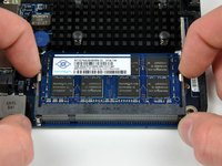
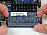
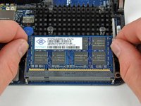
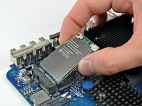
Spingi la memoria PRAM verso il centro della scheda logica e tirala fuori dal suo contenitore. Dovrai spingerla molto più in profondità di quanto ti aspetti per poterla tirarla fuori.
-
Quando inserisci la nuova memoria PRAM, assicurati che la faccia con la scritta sui lati sia rivolta verso il contenitore di plastica nero. Dovresti anche assicurarti che i connettori metallici facciano contatto con la memoria PRAM (puoi piegarli in avanti se non c'è contatto).
-


Per riassemblare il tuo dispositivo, segui queste istruzioni nell'ordine inverso.
Per riassemblare il tuo dispositivo, segui queste istruzioni nell'ordine inverso.
Annulla: non ho completato questa guida.
Altre 25 persone hanno completato questa guida.
Un ringraziamento speciale a questi traduttori:
100%

Questi traduttori ci stanno aiutando ad aggiustare il mondo! Vuoi partecipare?
Inizia a tradurre ›
Preparati per le riparazioni future
Acquista tutti


A spackle knife makes these steps go much faster.
jouniseppanen - Replica
A double sided letter opener or a thin non-serrated butter knife will suffice.
To prenent cosmetic blemishes, place a matchbook cover or similar thin cardboard on the outer perimeter under the “jimmy”.
Mike - Replica
Despite mentioning recommended tools at the top I think it’s really worthwhile making a point about narrow Philips screwdrivers at this point before people start putting the case apart.
Matt D - Replica