Salta al contenuto principale
Linksys WRT54GS v2 Antenna Ports Replacement

Linksys WRT54GS v2 Antenna Ports Replacement

Allian Roman

Allian Roman e 6 altri collaboratori

Ultimo aggiornamento il January 31, 2023

Nessuna stima
Moderato

Introduzione

Vai al passo 1

You will be desoldering the antenna ports.

Cosa ti serve

Strumenti

Mostra di più…

iFixit guadagna commissioni quando acquisti tramite questi link.
  1. Linksys WRT54GS v2 Antenna Ports Replacement, Front Case: passo 1, immagine 1 di 1
    • Turn the router over so that all four of its feet are facing upwards.

  2. Linksys WRT54GS v2 Antenna Ports Replacement: passo 2, immagine 1 di 1
    • Remove the rubber inserts inside the the two purple feet located on the router's front case.

    • This may be a challenge, so try the following two methods:

    • Use a plastic opening tool. Insert the flat end of the tool into the seam and slowly pry the rubber feet out.

    • Use a metal spudger. Insert the point of the metal spudger directly into the hole of the rubber feet and pry the insert out.

  3. Linksys WRT54GS v2 Antenna Ports Replacement: passo 3, immagine 1 di 1
    • Use a Phillips #2 Screwdriver to remove the two 5.8 mm screws holding the front case to the motherboard.

  4. Linksys WRT54GS v2 Antenna Ports Replacement: passo 4, immagine 1 di 1
    • Squeeze the sides of the router's backcase inward and pull off the purple front case. It is helpful to have a second person assist you for this step.

  5. Linksys WRT54GS v2 Antenna Ports Replacement, Motherboard: passo 5, immagine 1 di 1
    • Slide the board unit out and up.

  6. Linksys WRT54GS v2 Antenna Ports Replacement: passo 6, immagine 1 di 1
    • Flip the circuit board over and use a Phillips #2 Screwdriver to remove the 6.9mm screw holding the board to the back case.

    • Slide the back cover out and away from the circuit board.

  7. Linksys WRT54GS v2 Antenna Ports Replacement, Antenna Ports: passo 7, immagine 1 di 2 Linksys WRT54GS v2 Antenna Ports Replacement, Antenna Ports: passo 7, immagine 2 di 2
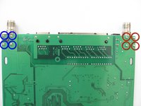
    • Turn the circuit board over and identify which solder connection you will desolder.

    • The solder connections shown in red hold the right antenna port in place. There is one more attachment for this antenna on the other side of the board.

    • The solder connections shown in blue hold the left antenna port in place. Desolder these 4 points to remove the antenna port.
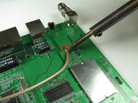
  8. Linksys WRT54GS v2 Antenna Ports Replacement: passo 8, immagine 1 di 1
    • Turn on your soldering iron and allow it to get to its highest temperature setting (minimum 600ºF).

  9. Linksys WRT54GS v2 Antenna Ports Replacement: passo 9, immagine 1 di 1
Conclusione

To reassemble your device, follow these instructions in reverse order.

Altre 2 persone hanno completato questa guida.

Allian Roman

Membro da: 10/12/11

276 Reputazione

5 Guide realizzate

Team

Cal Poly, Team 3-4, Regan Fall 2011 Membro di Cal Poly, Team 3-4, Regan Fall 2011

CPSU-REGAN-F11S3G4

4 Membri

12 Guide realizzate

1Commento della guida

Most do not have removeable antennae ports

tom - Replica

Aggiungi Commento

Visualizza Statistiche:

Ultime 24 Ore: 0

Ultimi 7 Giorni: 0

Ultimi 30 Giorni: 18

Tutti i Tempi: 3,307