Salta al contenuto principale
ProfiMixx 44 Disassembly

ProfiMixx 44 Disassembly

Justus Klingler

Justus Klingler e 2 altri collaboratori

Ultimo aggiornamento il August 7, 2021

40 minuti
Moderato
Guida fornita dalla comunità

Introduzione

Vai al passo 1

In case of broken lugs or screw holders, the two housing parts can be glued together. It is important to check that you have assembled everything correctly before gluing.

  1. ProfiMixx 44 Disassembly, Removing the scrapers: passo 1, immagine 1 di 3 ProfiMixx 44 Disassembly, Removing the scrapers: passo 1, immagine 2 di 3 ProfiMixx 44 Disassembly, Removing the scrapers: passo 1, immagine 3 di 3
    • Removing the five (TR15) scrapers

  2. ProfiMixx 44 Disassembly, Removing the housing: passo 2, immagine 1 di 2 ProfiMixx 44 Disassembly, Removing the housing: passo 2, immagine 2 di 2
    • Removing the first part of the housing

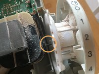
    • Removing the rotary wheel, important pay attention to the black component so that the nose in does not break off (green mark).

    • Removing the second part of the housing

  3. ProfiMixx 44 Disassembly, Assembly of the housing I: passo 3, immagine 1 di 3 ProfiMixx 44 Disassembly, Assembly of the housing I: passo 3, immagine 2 di 3 ProfiMixx 44 Disassembly, Assembly of the housing I: passo 3, immagine 3 di 3
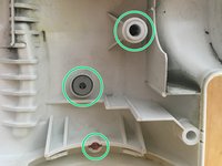
    • Make sure that the green marked elements are in the right place in both housings, the red element is only available once.

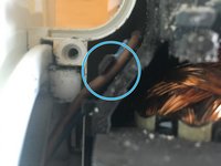
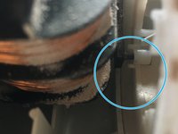
    • Make sure that the two strands run as marked in blue.

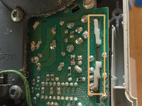
    • The white element must be in the rear position. (marked in orange)

  4. ProfiMixx 44 Disassembly, Assembly of the housing II: passo 4, immagine 1 di 3 ProfiMixx 44 Disassembly, Assembly of the housing II: passo 4, immagine 2 di 3 ProfiMixx 44 Disassembly, Assembly of the housing II: passo 4, immagine 3 di 3
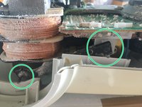
    • Lift the motor-gearbox-unit a little bit upwards so that you can insert the black element with the nose into the hole of the white element. (marked in green)

    • Insert the nose of the black element into the hole of the rotary switch, making sure it is oriented as shown.

    • Gently move the rotary switch so that it fits into the slot in the housing. (marked in blue)

    • Then you can tighten the upper housing part with the five screws (TR15).

Linea Traguardo

0 Commenti

Aggiungi Commento

Visualizza Statistiche:

Ultime 24 Ore: 0

Ultimi 7 Giorni: 15

Ultimi 30 Giorni: 59

Tutti i Tempi: 1,023