Introduzione
This is a prerequisite-only guide! This guide is part of another procedure and is not meant to be used alone.
Use this guide to replace the motherboard in your Samsung Galaxy Tab S7+
For your safety, discharge the battery below 25% before disassembling your tablet. This reduces the risk of fire if the battery is accidentally damaged during the repair. If your battery is swollen, take appropriate precautions.
There is a significant chance that you may break the unreinforced and fragile display panel during this procedure. Be sure to apply plenty of heat and be extremely careful during the prying stage.
You'll need replacement adhesive in order to complete this repair.
Cosa ti serve
-
-
Apply a heated iOpener to the bottom edge of the device to loosen the adhesive underneath.
-
-
-
While you're waiting for the adhesive to loosen, note the following:
-
There's a long circuit board attached to the screen that sits parallel to the bottom edge.
-
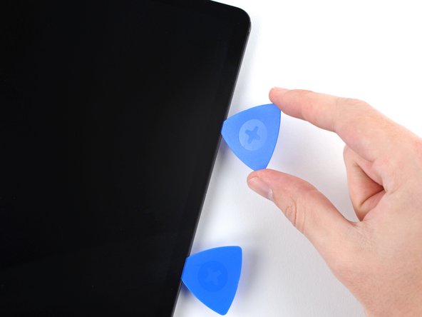
This image shows an example of the display separating from the glass panel.
-
-
-
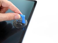
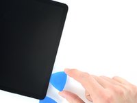
Once the screen is warm to touch, apply a suction handle to the bottom edge of the screen and as close to the edge as possible.
-
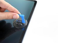
Lift the screen with the suction handle to create a small gap between the screen and the frame.
-
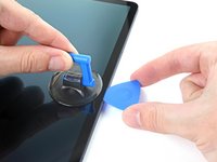
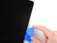
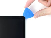
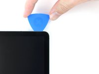
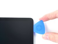
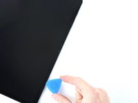
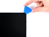
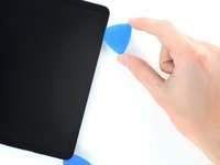
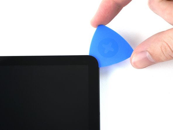
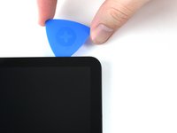
Insert an opening pick into the gap between the frame and the screen.
-
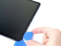
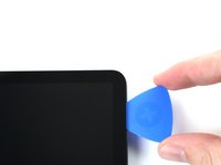
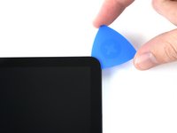
Leave the opening pick in place to prevent the adhesive from resealing.
-
-
-
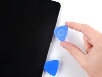
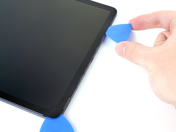
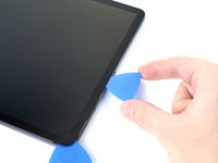
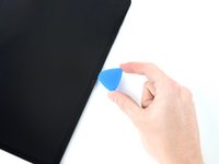
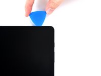
Insert a new opening pick into the gap you created.
-
Slide the new pick along the bottom edge of the device towards the bottom-right corner.
-
-
-
Apply a heated iOpener to the right edge of the device to loosen the adhesive underneath.
-
-
-
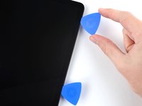
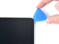
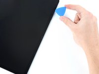
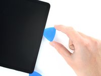
Rotate the opening pick around the bottom-right corner of the device.
-
Leave the opening pick in place to prevent the adhesive from resealing.
-
-
-
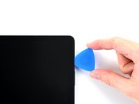
Insert a new opening pick into the gap you created.
-
Slide the new pick along the right edge of the device towards the top-right corner.
-
-
-
Apply a heated iOpener to the top edge of the device to loosen the adhesive underneath.
-
-
-
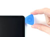
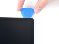
Rotate the opening pick around the top-right corner of the device.
-
Leave the opening pick in place to prevent the adhesive from resealing.
-
-
-
Insert a new opening pick into the gap you created.
-
Slide the new pick along the top edge of the device towards the top-left corner.
-
-
-
Apply a heated iOpener to the left edge of the device to loosen the adhesive underneath.
-
-
-
Rotate the opening pick around the top-left corner of the device.
-
Leave the opening pick in place to prevent the adhesive from resealing.
-
-
-
-
Insert a new opening pick into the gap you created.
-
Slide the new pick along the left edge of the device towards the bottom-left corner.
-
-
-
Rotate the opening pick around the bottom-left corner of the device.
-
Leave the opening pick in place to prevent the adhesive from resealing.
-
-
Attrezzo utilizzato in questo passaggio:Tweezers$4.99
-
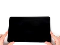
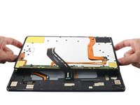
With the top of the device facing you, pull the screen up and away from you like you're opening a book.
-
Rest the screen upside down and parallel to the frame before continuing.
-
This is a good point to power on your tablet and test all functions before sealing it up. Be sure to power your tablet back down completely before you continue working.
-
Remove any adhesive chunks with a pair of tweezers or your fingers. Use some high concentration (over 90%) isopropyl alcohol to wipe away any adhesive residue.
-
If you're using custom-cut adhesives, follow this guide. If you're using double-sided tape, follow this guide.
-
-
-
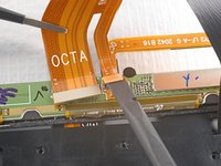
Use the flat end of a spudger to pry up and disconnect the display cable's press connector secured to the screen.
-
-
-
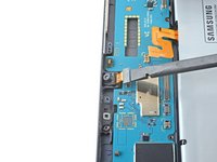
Use a Phillips #00 screwdriver to remove the fifty 3 mm-long screws securing the frame bracket to the frame.
-
Bottom left = 9 screws
-
Bottom right = 14 screws
-
Top right = 12 screws
-
Top left = 15 screws
-
-
-
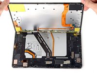
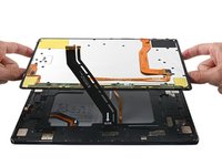
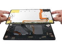
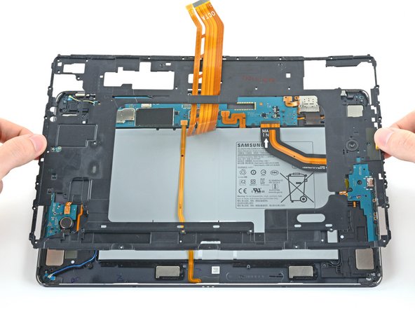
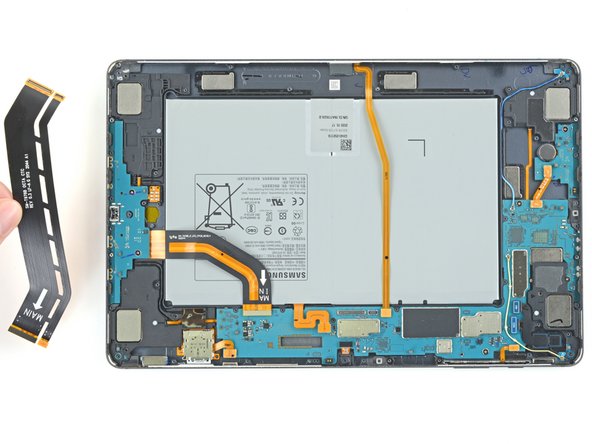
Lift the frame bracket away from the frame, making sure to thread the display cable through its socket.
-
-
-
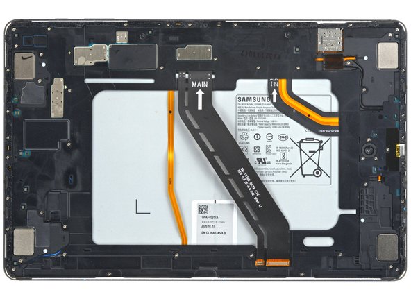
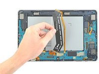
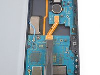
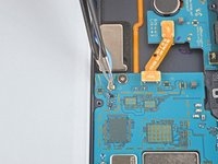
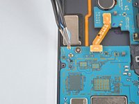
Use the flat end of a spudger to pry up and disconnect the battery's press connector secured to the motherboard.
-
-
-
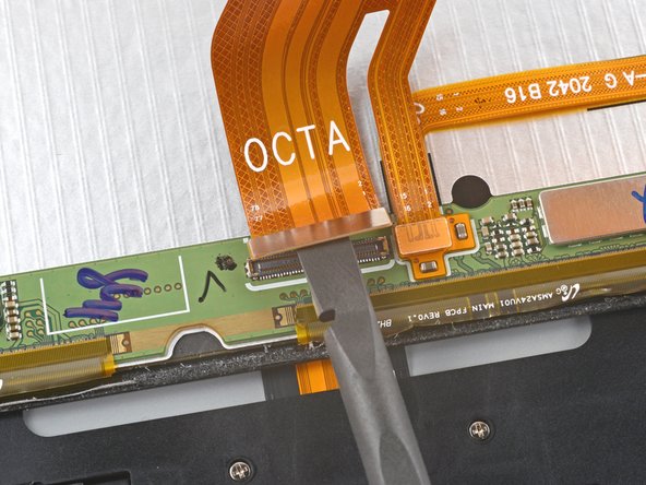
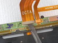
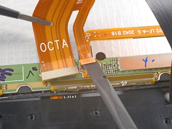
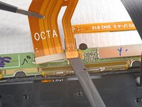
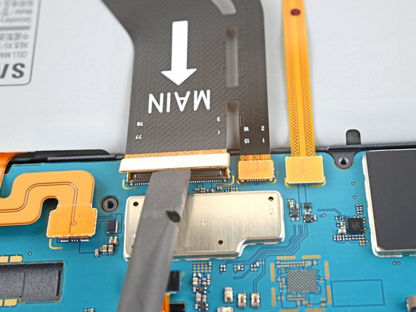
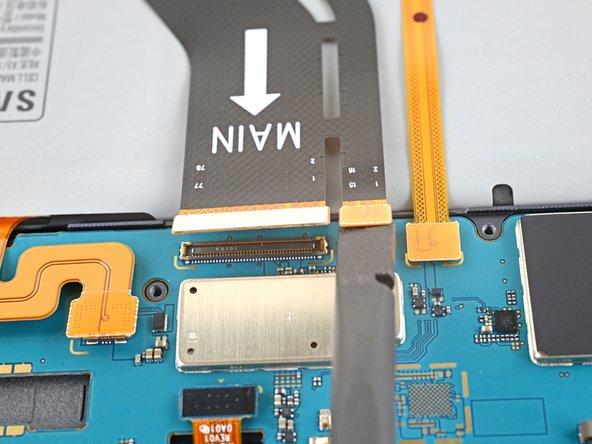
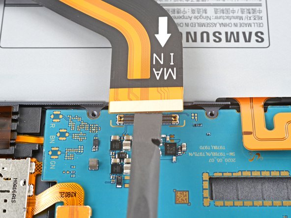
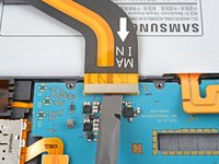
Use the flat end of a spudger to pry up and disconnect the display cable's press connector secured to the motherboard.
-
Repeat for the fingerprint sensor cable attached to display cable.
-
-
-
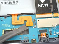
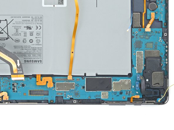
Use the flat end of a spudger to pry up and disconnect the daughterboard interconnect cable's press connector secured to the motherboard.
-
-
-
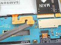
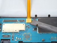
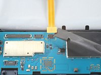
Use the flat end of a spudger to pry up and disconnect the keyboard dock port cable's press connector secured to the motherboard.
-
-
Attrezzo utilizzato in questo passaggio:Tweezers$4.99
-
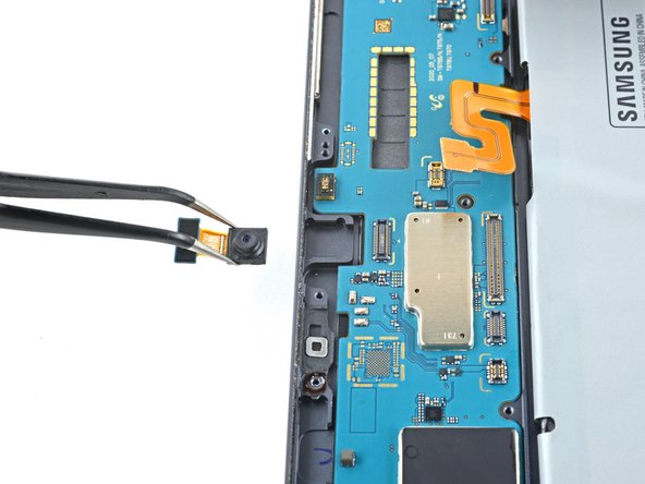
Use the flat end of a spudger to pry up and disconnect the front camera's press connector secured to the motherboard.
-
Use tweezers, or your fingers, to remove the front camera.
-
-
-
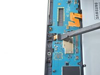
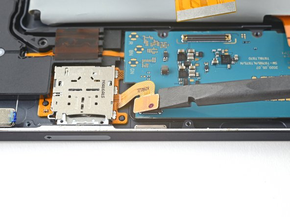
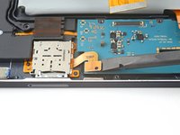
Use the flat end of a spudger to pry up and disconnect the microSD card reader's press connector secured to the motherboard.
-
-
-
Use the flat end of a spudger to pry up and disconnect the rear camera's two press connectors secured to the motherboard.
-
-
-
Use the flat end of a spudger to pry up and disconnect the power button cable's press connector secured to the motherboard.
-
-
-
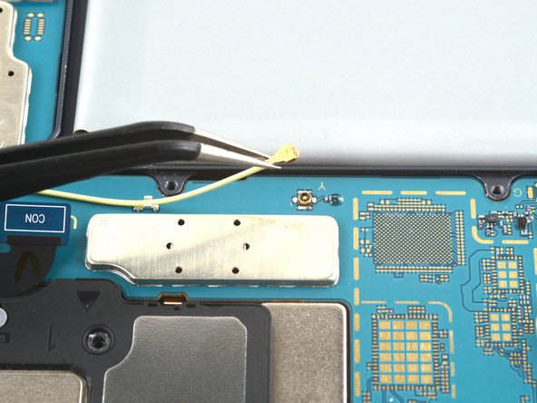
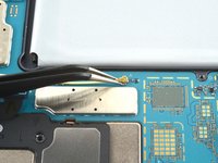
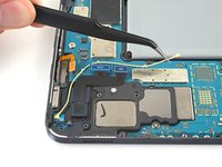
Use the point of a spudger to carefully pry up and disconnect the bottom-right loudspeaker's yellow coaxial cable from the motherboard.
-
-
-
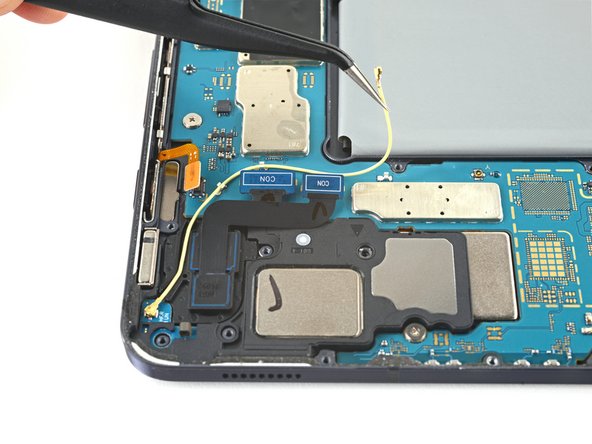
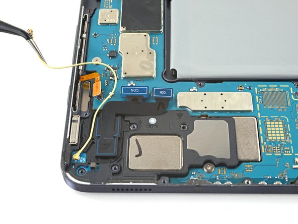
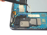
Pull the coaxial cable away from the frame, making sure the cable is completely unthreaded from the motherboard.
-
-
-
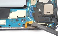
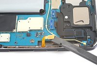
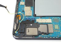
Use the flat end of a spudger to pry up and disconnect the interconnect cable's press connector secured to the motherboard.
-
-
-
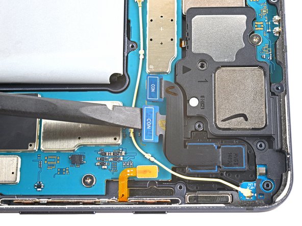
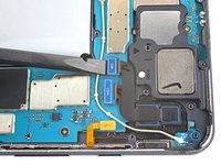
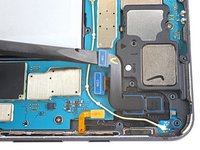
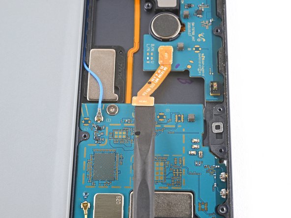
Use the point of a spudger to carefully pry up and disconnect the top-right loudspeaker's blue coaxial cable from the motherboard.
-
-
-
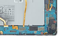
Use a Phillips #00 screwdriver to remove the three 2 mm screws securing the motherboard to the frame.
-
-
-
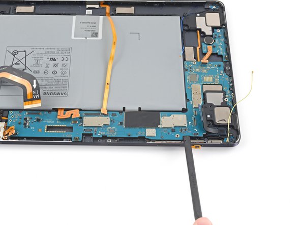
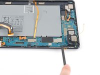
Insert a spudger into a gap between the motherboard and the frame.
-
Pry up with the spudger to release the motherboard from its clips.
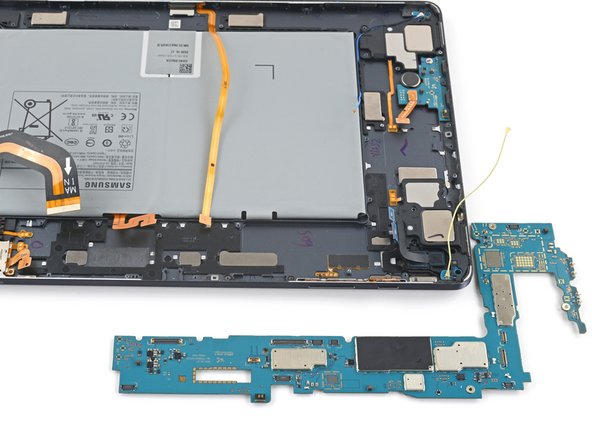
-
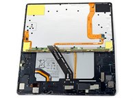
Remove the motherboard.
-


To reassemble your device, follow these instructions in reverse order.
Compare your new replacement part to the original part—you may need to transfer remaining components or remove adhesive backings from the new part before you install it.
Repair didn’t go as planned? Try some basic troubleshooting, or ask our Samsung Galaxy Tab S7+ Answers community for help.

