Salta al contenuto principale
Astak Mole Camera Head Replacement

Astak Mole Camera Head Replacement

Bryan

Bryan e 5 altri collaboratori

Ultimo aggiornamento il February 28, 2021

10 minuti
Difficile
Attrezzi Non Corretti
Fallo a Fettine

Introduzione

Vai al passo 1

In order for you to replace the camera head, you will have to separate the base and the camera head by disconnecting some wires that lead from the head to the motherboard.

Cosa ti serve

Strumenti

  • Spudger
    Spudger
  • Phillips #1 Screwdriver
    Phillips #1 Screwdriver
  1. Astak Mole Camera Head Replacement, Lower Case: passo 1, immagine 1 di 1
    • Remove the four bottom tabs in order to access the bottom screws.

  2. Astak Mole Camera Head Replacement: passo 2, immagine 1 di 1
    • Remove all four 14 mm Phillips #1 screws.

  3. Astak Mole Camera Head Replacement: passo 3, immagine 1 di 1
    • Remove the SD card.

  4. Astak Mole Camera Head Replacement: passo 4, immagine 1 di 1
    • Pry up the motherboard on the four points using a spudger.

    • The regular black nylon spudger should be used whenever possible, especially around sensitive internal components.

  5. Astak Mole Camera Head Replacement: passo 5, immagine 1 di 1
    • Gently pull back the motherboard to expose many of the component's wired connections.

  6. Astak Mole Camera Head Replacement, Camera Head: passo 6, immagine 1 di 1
    • Unscrew the three screws connecting the base to the camera head with the PH1 size Phillips head bit.

    • Screw measurements: Length=7.0mm.

    • The third screw can be exposed by rotating the camera head.

    • Do not force the camera head farther than it will allow you.

  7. Astak Mole Camera Head Replacement: passo 7, immagine 1 di 1
    • Unscrew indicated Phillips head screws using the PH1 Phillips head bit to free wires.

    • Screw measurements: Length=3.5mm

  8. Astak Mole Camera Head Replacement: passo 8, immagine 1 di 3 Astak Mole Camera Head Replacement: passo 8, immagine 2 di 3 Astak Mole Camera Head Replacement: passo 8, immagine 3 di 3
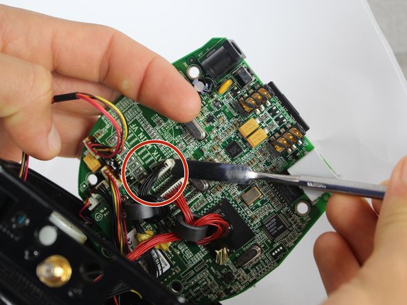
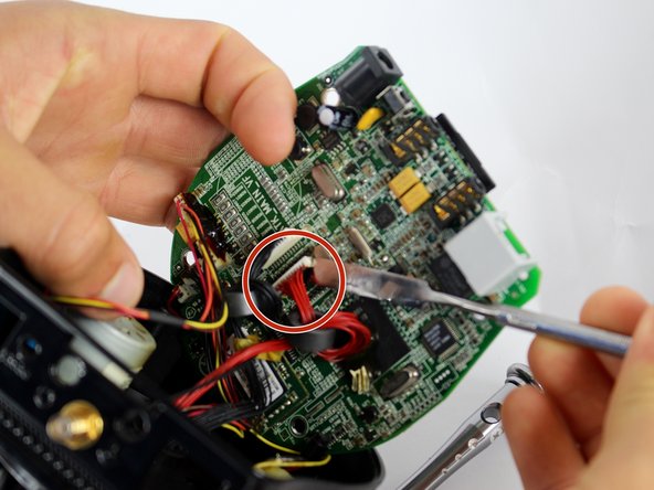
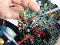
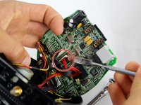
    • Separate the three indicated outputs from the motherboard with metal spudger.

    • There is electrical adhesive on the output. This can be easily separated with the metal spudger.

    • The regular black nylon spudger should be used whenever possible, especially around sensitive internal components.

  9. Astak Mole Camera Head Replacement: passo 9, immagine 1 di 1
    • Separate the wire from CPU by cutting adhesive with metal spudger.

    • It is advised to reapply adhesive to wired connections during reassembly, and to re-attach wires to CPU to prevent disconnection and loose wires inside device.

    • Be careful not to damage the CPU in the process. This is not a wired connection.

Conclusione

To reassemble your device, follow these instructions in reverse order.

Bryan

Membro da: 09/15/16

104 Reputazione

1 Guida realizzata

Team

USF Tampa, Team 2-2, Blackwell Fall 2016 Membro di USF Tampa, Team 2-2, Blackwell Fall 2016

USFT-BLACKWELL-F16S2G2

4 Membri

12 Guide realizzate

0 Commenti

Aggiungi Commento

Visualizza Statistiche:

Ultime 24 Ore: 4

Ultimi 7 Giorni: 6

Ultimi 30 Giorni: 19

Tutti i Tempi: 555