
Accessing LCD Screen
Introduzione
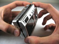
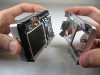
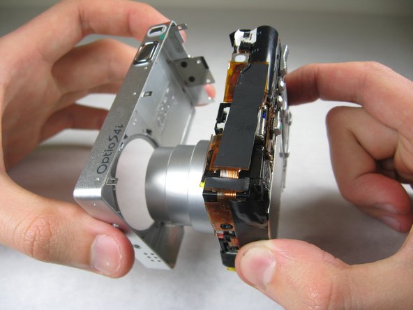
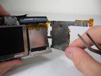
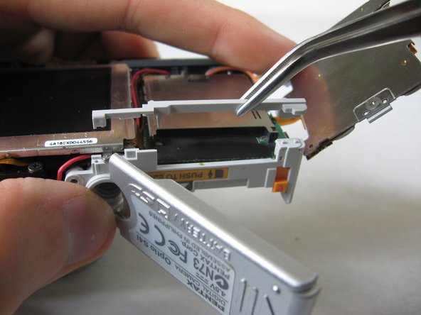
Vai al passo 1In this guide, you will be able to access and remove the LCD screen from the camera's frame.
Cosa ti serve


-
-
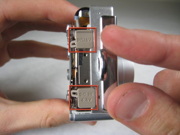
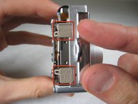
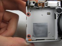
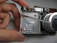
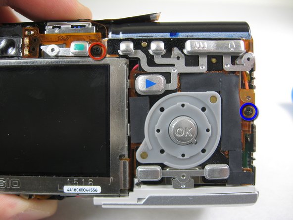
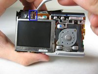
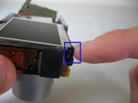
Remove the following screws:
-
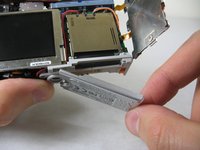
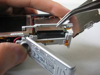
Two silver 3.15mm Phillips #00 screws on the right side of the camera
-
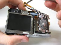
Two silver 2.08mm Phillips #00 screws on the left side of the camera
-
-
-
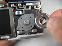
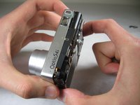
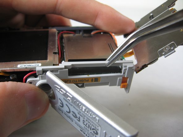
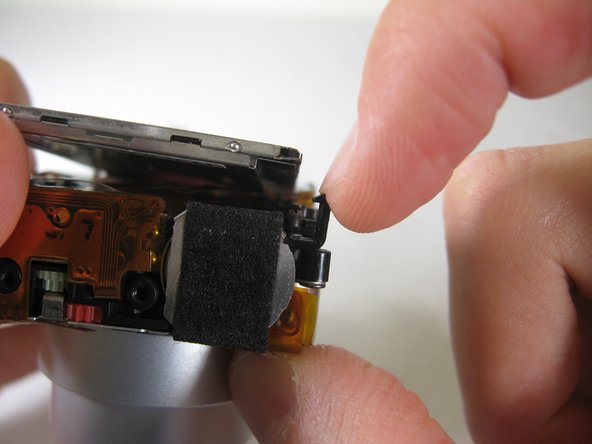
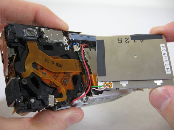
On the front of the camera, in battery case, remove screws indicated:
-
Two black 2.05mm Phillips #00 screws
-
-


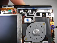


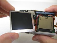
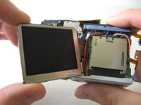

To reassemble your device, follow these instructions in reverse order.
To reassemble your device, follow these instructions in reverse order.
Preparati per le riparazioni future
Acquista tutti


Team

Cal Poly, Team 4-29, Regan Winter 2011 Membro di Cal Poly, Team 4-29, Regan Winter 2011
CPSU-REGAN-W11S4G29
3 Membri
10 Guide realizzate