Avviso: Stai modificando una guida prerequisita. Tutte le modifiche avranno effetto su tutte le guide che includono questo passo.
Traduzione in corso passo 5
Passo 5


-
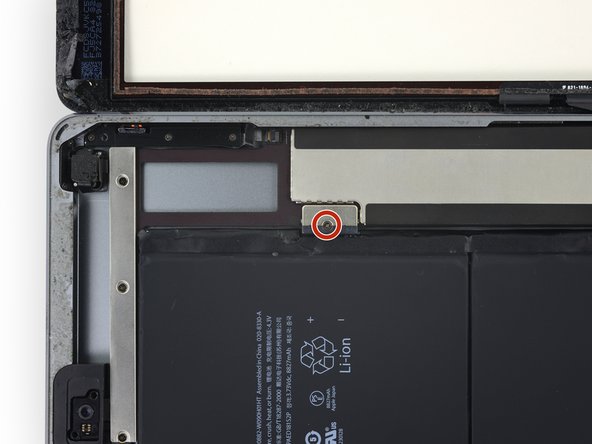
Remove the single 2.3 mm Phillips #000 screw securing the battery connector to the logic board.
-
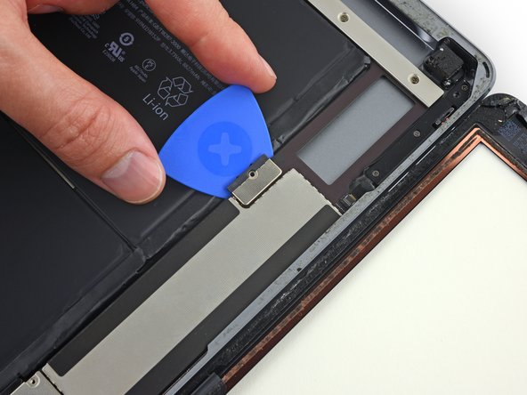
Slide the battery blocker underneath the logic board's battery connector at a 35 degree angle.
-
Leave the battery blocker in place as you work.
| [* red] Remove the single 2.3 mm Phillips #000 screw securing the battery connector to the logic board. | |
| [* icon_note] To reduce the risk of a short, you can use a battery isolation pick to disconnect the battery. | |
| - | [* black] Slide a battery isolation pick underneath the battery connector area of the logic board, and leave it in place while you work. |
| + | [* black] Slide the battery blocker underneath the logic board's battery connector at a 35 degree angle. |
| + | [* icon_note] Don't push the battery blocker underneath the connector with excessive force. If you're having trouble fitting the battery blocker underneath the logic board, you can try [guide|143682|using a playing card|new_window=true] to disconnect the battery instead. |
| + | [* icon_note] The battery blocker or playing card ideally should slide under the logic board without encountering any blockages. After insertion, it should rest at a 15 degree angle. |
| + | [* black] Leave the battery blocker in place as you work. |
I tuoi contributi sono usati su licenza in base alla licenza open source Creative Commons.