Introduzione
Questa procedura risolve i problemi di lettura dei CD.
IMPORTANTE: I passaggi da 11 a 16 non hanno alcuna utilità qui e serviranno solo ad allungare il processo. Per risparmiare tempo e sforzo, salta direttamente dal passo 10 al passo 17.
Cosa ti serve
-
-
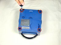
Ruota il GameCube in modo che la faccia inferiore sia rivolta verso l'alto.
-
Utilizza il cacciavite Gamebit da 4,5 mm per rimuovere tutte e quattro le viti.
-
-
-
Con la faccia inferiore del GameCube rivolta verso l'alto e le viti rimosse, tira attentamente la copertura esterna della console via dalla copertura superiore.
-
Sposta il GameCube in modo che l'interno sia rivolto verso l'alto.
This can also be done whilst being in the normal upright position after all 4 of the 4.5mm Gamebit screws have been removed. Pull the top of the shell directly upwards and it should slide off easily.
Less chance of snagging any wires or parts.
-
-
-
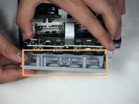
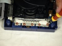
Premi delicatamente sui clip posizionati su entrambi i lati del pannello posteriore.
-
Rimuovi con attenzione il pannello posteriore dal GameCube.
A second picture clearly showing which direction to pull the back panel away from the unit would be nice.
-
-
-
Sgancia attentamente le porte dei controller sulla parte anteriore della console.
well... what happens if accidentally i disconnected it?
presumably nothing major. The CMOS battery is attached to the controller ports, so the most i'd expect is that the gamecube loses it's date/time setting. As long as you reset that before jumping into animal crossing or something, you should be fine. I'm currently doing a teardown of my gamecube, and if something does prove to have gone wrong, i'll report back.
sigoshi -
okay, i finished putting it back together. gamecube works fine and surprisingly still remembers what year it is. boots into smash bros and shows memory card contents fine.
sigoshi -
-
-
-
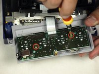
Usa un cacciavite a croce Phillips per svitare le 2 viti che si trovano sul retro delle prese dei controller.
-
Separa attentamente la copertura esterna grigia delle porte dei controller e della scheda logica.
must do this?
That step is not needed for the laser replacement.
Love ur labeling and legends. Good on ya
Not a necessary step
-
-
-
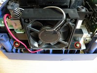
La parte sinistra della console contiene la ventola e il suo alloggio.
-
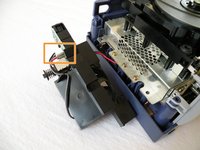
Svita attentamente le due viti che fissano la ventola al suo alloggio.
-
Non scollegare i cavi rosso e nero della ventola dalla console. Indicato in arancione
Why can't the fan wire be detached?
It can, but you might not want to
-
-
-
-
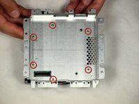
Il lettore CD è fissato ad una placca in metallo.
-
Usando un cacciavite a croce Phillips #2, svita le dodici viti attorno al bordo esterno del lettore CD.
Are these 12 screws the exact same kind like the 2 that were on the fan?
Yes! As far as I can tell anyway. Makes sense, too since opposite the fan you have five of the same holes as well.
-
-
-
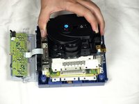
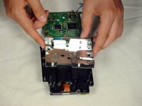
Separa attentamente il gruppo del lettore CD dal resto del GameCube.
-
Il gruppo del lettore CD è fissato alla scheda madre sottostante da una presa: potresti dover fare una certa forza per rimuovere attentamente il gruppo.
-
La placca in metallo e il lettore CD resteranno attaccati.
-
-
-
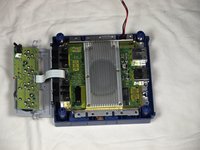
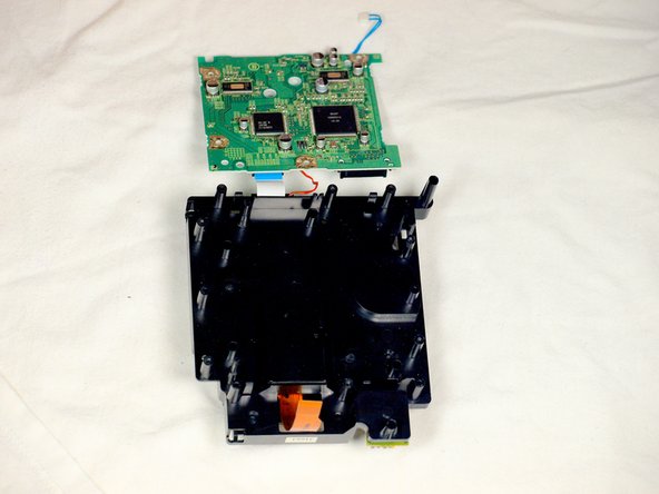
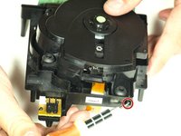
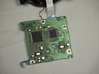
A questo punto, il gruppo del lettore CD dovrebbe essere separato dal tuo GameCube (immagine 1).
-
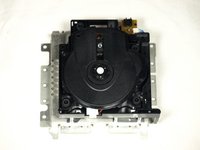
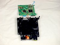
Gira il gruppo del lettore CD a faccia in giù.
-
Rimuovi le sei viti con un cacciavite a croce di dimensioni #1.
-
Solleva delicatamente e rimuovi la piastra metallica.
If you are just doing the lens power adjustment, from this step skip straight to step 17. Steps 11-16 are unnecessary unless you are replacing the lens completely.
-
-
-
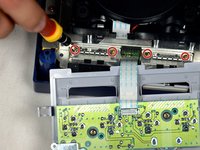
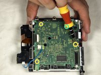
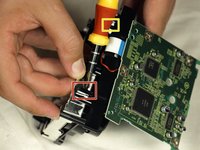
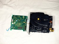
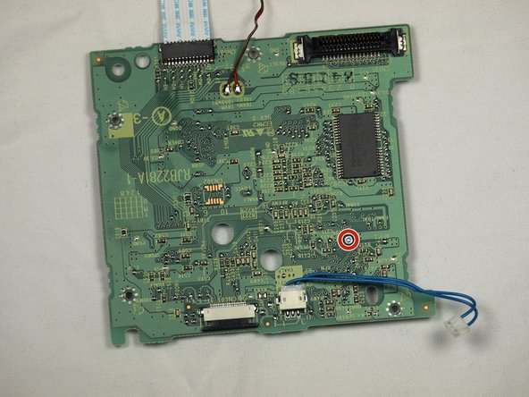
Scollega il cavo blu tirandolo delicatamente.
-
Scollega il cavo marrone. Per farlo tira delicatamente via l'aletta nera dalla plastica bianca. Così allenterai la tensione sul cavo marrone, potendolo sfilare dall'aletta.
-
Rimuovi le quattro viti Phillips #1 che collegano la scheda circuito all'insieme dell'unità ottica.
A helpful addition/change to this step would be to include a photo of where/how to remove the brown ribbon cable (maybe also include this terminology in the text, instead of just “cable”). Furthermore, the yellow box to indicate the blue cable highlights everything except the part that you need to remove, which is a little confusing.
Thanks!
Ben
I cannot get the 4 little screws to go back into the board once removed. There is nothing for them to bite into - how do I get this board put back together?
I had this same issue — until I realized that the metal plate goes back on BEFORE the circuit board XD. Once you out the metal plate back on and put the circuit board on top of that, the screws should go in okay.
-
-
-
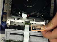
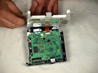
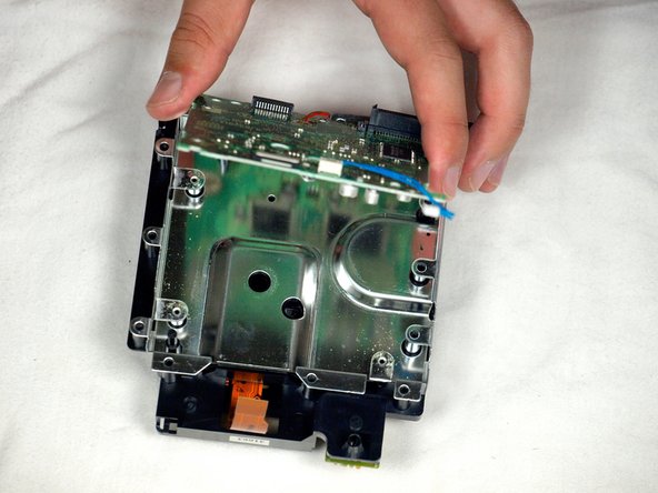
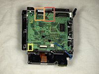
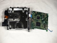
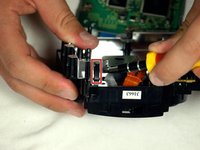
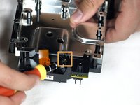
Rilascia la piccola clip che tiene giù la scheda.
-
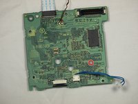
Rimuovi delicatamente la scheda logica (il grande quadrato verde) come mostrato nelle tre immagini.
-
Cavo rosso
-
Cavo a nastro bianco
What would happen if I accidentally separated the white ribbon cable... because I watched a video of some guy going through this same process. Separated all the cables and his worked. My cube stopped reading disks recently. Laser is calibrated properly. Begins to spin then stops
Ps
Is there anyway I can save my cube
I'm just guessing here, but I think they mean there's no need to separate those cables to complete the repair—just be careful not to pull or stress them. Like you said, nothing bad will happen if you choose to disconnect a couple cables. As for what's wrong with your cube, you might want to try asking your question over in the Answers forum.
There is a small tab to the left of the red wire that you need to pull out to release the circuit board.
Why do we need further disassembly that this ? The potentiometer is already accessible at this point. Why do we need to tear down the lens from it’s slot in step 16 ?
Good question! I’m wondering the same thing.
You don’t. You can stop here if you’re doing the laser potentiometer calibration.
jweeman -
-
-
-
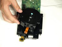
Usa un cacciavite a testa piatta per rilasciare attentamente i quattro ganci in plastica che tengono insieme il gruppo del lettore CD.
-
Usa con attenzione un cacciavite come leva per svitare e rilasciare l'ultima clip.
Since this step uses a flathead screwdriver, it might be useful to include that in the list of required tools at the top.
-
-
-
Usa un cacciavite a testa piatta per rilasciare i due ganci sulla metà posteriore del gruppo del lettore CD.
-
L'ultimo gancio non deve essere rilasciato: La metà superiore del gruppo del lettore CD si sfilerà da quella inferiore.
-
Rimuovi la metà superiore del gruppo del lettore CD dalla base.
-
-
-
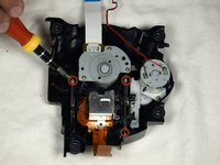
Dopo aver staccato la metà superiore del gruppo del lettore CD, girala a faccia in giù.
-
Usando un cacciavite a croce Phillips #1, svita attentamente le ultime tre viti vicino alle barre del gruppo della lente.
-
Estrai le ultime tre viti e rimuovi l'insieme della lente.
what kind of screws are these on the laser lens i lost one and need to buy new ones cause i cant find the 3rd
we're replacing the laser tho
-
-
-
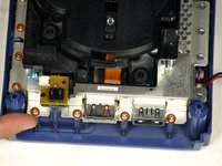
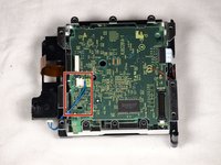
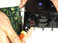
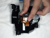
Ruota il gruppo in modo che la scheda logica verde sia rivolta verso di te come mostrato nella prima immagine.
-
Gira la scheda a faccia in giù in modo che sia orientata come nella seconda immagine.
-
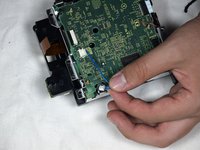
Usando un cacciavite a croce Phillips #1, gira la piccola manopola molto leggermente in senso antiorario, di qualche grade, al massimo di un quarto di giro.
Isn't it supposed to be counter clockwise? I read somewhere that turning it clockwise weakens the laser.
Does anyone know the initial ohm potentiometer setting on Nintendo Gamecube DOL-001 (factory) on the pcb driver (RJB2281A-1 POT 0-900 OHM) THANK YOU
You don't. The author just duct taped a step to the end of the laser replacement guide and called it a day
-


Per rimontare il tuo dispositivo, segui le istruzioni in ordine inverso.
Per rimontare il tuo dispositivo, segui le istruzioni in ordine inverso.
Annulla: non ho completato questa guida.
Altre 29 persone hanno completato questa guida.
Un ringraziamento speciale a questi traduttori:
100%

Questi traduttori ci stanno aiutando ad aggiustare il mondo! Vuoi partecipare?
Inizia a tradurre ›
Team

Cal Poly, Team 6-2, Maness Fall 2009 Membro di Cal Poly, Team 6-2, Maness Fall 2009
CPSU-MANESS-F09S6G2
4 Membri
45 Guide realizzate
6 Commenti
I don't understand why you have steps 11-17. In step 10, you can clearly see the board with the screw that needs adjusting. Taking apart the rest of the GameCube is utterly unnecessary. After following the guide in full, I thought, 'Why did I just dismantle all that other stuff when I didn't even NEED to?'
Once the assembly is removed from the metal covering the board, it is a simple matter to turn the screw to increase the laser strength. I did this after my initial adjustment didn't work. I ignored steps 11-17 and everything works perfectly now. My old games which simply would not load, now do. Thanks for the advice leading up to step 10 though. That part was helpful.
I wouldn't say it's a quarter of a turn, a few degrees clockwise do the trick. I tried a quarter of a turn the first time and it made the disk unit useless as it didn't recognise any gamecube disk.
Thanks for the detailed pictures! I was able to get everything taken apart, and fixed the read error I was having after a couple of readjustments.
One important note: the lens screw should be turned counter-clockwise, not clockwise. A quarter turn is also likely to be too much; better to adjust a few degrees at a time and test repeatedly until the right setting is found.
gameFAQs.com has a lens calibration guide, with notes on how to reassemble the GameCube for testing without screwing everything back together.
I also agree that steps 11-17 can be skipped, as well as step 5 to remove the controller ports.
Steps 11+ are definitely not needed and 1/4 turn is more than 200ohms, way too much. It has to be moved by a hair (almost literally), the potentiometer is extremely sensitive. And I would personally recommend some form of multimeter, as to not go turning that screw blindly.
Great guide, this fixed my problem. Would like to be clarified if you need to follow steps 11-17 make the power adjustment.
Hell yes dude, thank you! The console I got from my grandma with SA2B as a preteen finally stopped reading discs completely yesterday after having trouble on and off for years, I was afraid I'd have to replace the entire drive assembly but adjusting the lens power worked!
Also, to complete step 6, the fan is a little tricky to remove, at least on a DOL-001 US console. You have to sort of rotate the fan assembly outward clockwise, by pulling the front of the fan out to the left a bit, so the plastic can clear the drive assembly.