Salta al contenuto principale

Nintendo DSi Outer Casing Replacement

Guida Archiviata
Questa guida è mantenuta solo per scopi storici. Usa la versione aggiornata della guida per eseguire la riparazione.

Cosa ti serve

  1. Attenzione: i passaggi 1-2 provengono da una guida contrassegnata come in corso.

    Nintendo DSi Outer Casing Replacement, Battery: passo 1, immagine 1 di 1
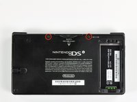
    • Loosen the two screws on the battery panel. Then lift the panel up to remove it.

  2. Nintendo DSi Outer Casing Replacement: passo 2, immagine 1 di 1
    • L Button.

    • Top of the battery pack.

    • To remove the battery pack, place your fingernail or a spudger at the top of the battery near the L button. Gently lift the battery out.

  3. Nintendo DSi Outer Casing Replacement, Lower Case Assembly: passo 3, immagine 1 di 2 Nintendo DSi Outer Casing Replacement, Lower Case Assembly: passo 3, immagine 2 di 2
    • Two screws are hidden underneath two rubber feet highlighted in red.

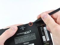
    • Use the tip of a spudger to pry the rubber feet out of the lower case.

  4. Nintendo DSi Outer Casing Replacement: passo 4, immagine 1 di 1
    • Remove the following screws securing the lower case to the body of the DSi:

    • Six 5.2 mm Phillips #00 screws.

    • One 2.7 mm Phillips #00 screw.

  5. Nintendo DSi Outer Casing Replacement: passo 5, immagine 1 di 3 Nintendo DSi Outer Casing Replacement: passo 5, immagine 2 di 3 Nintendo DSi Outer Casing Replacement: passo 5, immagine 3 di 3
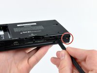
    • Insert the spudger in between the lower casing and lower panel near the top right corner of the DSi.

    • Carefully run the spudger along the edge of the outer casing, creating an opening between the body and the casing.

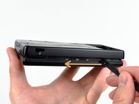
    • Continue running the spudger around the body of the DSi until the majority of the lower case has been separated.

  6. Nintendo DSi Outer Casing Replacement: passo 6, immagine 1 di 2 Nintendo DSi Outer Casing Replacement: passo 6, immagine 2 di 2
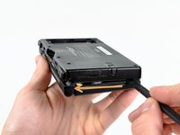
    • Carefully lift the lower casing from its bottom edge.

    • The lower case is still attached to the motherboard by the volume and SD board cable highlighted in red. Do not try to completely remove the lower case of the DSi yet.

    • Pry the volume and SD board cable up from its socket on the motherboard using a spudger.

    • Once the cable is completely removed, then you may take off the entire outer casing.

  7. Attenzione: i passaggi 7-8 provengono da una guida contrassegnata come in corso.

    Nintendo DSi Outer Casing Replacement, Disconnecting Nintendo DSi Battery Board: passo 7, immagine 1 di 1
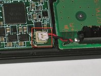
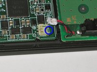
    • Flip up the black latch and disconnect the D-Pad/Power Button ribbon cable.

  8. Nintendo DSi Outer Casing Replacement: passo 8, immagine 1 di 3 Nintendo DSi Outer Casing Replacement: passo 8, immagine 2 di 3 Nintendo DSi Outer Casing Replacement: passo 8, immagine 3 di 3
    • The power connector (with red and black wires) is difficult to remove without damaging it, unless you take a moment and understand how it works. Look at all of the photos for this step before continuing.

    • The connector is two pieces -- a white "male" piece (connected to the wires), and a beige "female" part (soldered to the main board).

    • There is a small "notch" in the female part, to give you a place to insert a small flat-head screwdriver. Put the corner of your screwdriver in there, and twist it gently to push the white part up (away from the main board). Do not try to pull it to the right (towards the battery board).

    • If it does not lift easily, try again with a smaller screwdriver. You might be pulling the female connector off the board, which will be difficult to repair.

  9. Attenzione: i passaggi 9-10 provengono da una guida contrassegnata come in corso.

    Nintendo DSi Outer Casing Replacement, Motherboard: passo 9, immagine 1 di 2 Nintendo DSi Outer Casing Replacement, Motherboard: passo 9, immagine 2 di 2
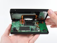
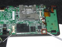
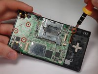
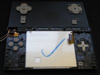
    • Remove 4 Phillips screws from the board.

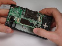
    • Lift the main board from the bottom end and flip it over to reveal the last connector.

    • Keep the main board fairly close to the case, making sure not to damage the last ribbon cable holding it in place.

  10. Nintendo DSi Outer Casing Replacement: passo 10, immagine 1 di 1
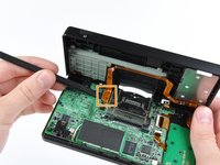
    • Disconnect the ribbon cable by gently using a plastic opening tool to flip up the black connector latch. The cable should easily slide out from the connector.

    • The motherboard should now be free from the rest of the device.

  11. Attenzione: i passaggi 11-13 provengono da una guida contrassegnata come in corso.

    Nintendo DSi Outer Casing Replacement, Disassembling Nintendo DSi Bottom case: passo 11, immagine 1 di 1
    • Remove the rubber front-panel button membranes from the device. Pay careful attention to where the buttons go, so you can replace them correctly.

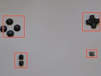
    • A/B/X/Y button assembly

    • Select/Start button assembly

    • D-pad

    • Power button

  12. Nintendo DSi Outer Casing Replacement: passo 12, immagine 1 di 2 Nintendo DSi Outer Casing Replacement: passo 12, immagine 2 di 2
    • Remove the plastic buttons and keep them in a safe place.

    • All of the buttons have "key" notches to prevent them from being inserted incorrectly (backwards or in the wrong place), but it can take a while to figure out where everything goes if they get shuffled around.

  13. Nintendo DSi Outer Casing Replacement: passo 13, immagine 1 di 2 Nintendo DSi Outer Casing Replacement: passo 13, immagine 2 di 2
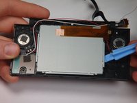
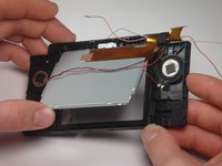
    • Flip the case open, and push the lower screen assembly out of the frame.

  14. Attenzione: i passaggi 14-23 provengono da una guida contrassegnata come in corso.

    Nintendo DSi Outer Casing Replacement, Top LCD Screen: passo 14, immagine 1 di 1
    • To make the repair easier, we recommend removing the bottom LCD screen prior to replacing the top LCD screen.

    • Using a spudger, or similar tool, pry out the 4 square screw covers.

  15. Nintendo DSi Outer Casing Replacement: passo 15, immagine 1 di 1
    • Remove 4 Phillips screws with a #00 Phillips screwdriver.

  16. Nintendo DSi Outer Casing Replacement: passo 16, immagine 1 di 1
    • Place a plastic opening tool between the front panel and top edge of the outer case. Slide the tool along the edge as needed to prop open the case.

    • With the screen facing you, slide the screen side down with your thumbs to separate the screen from the cover.

  17. Nintendo DSi Outer Casing Replacement: passo 17, immagine 1 di 1
    • Remove the antenna from the bottom left of the device.

    • Remove the microphone from the top of the frame.

  18. Nintendo DSi Outer Casing Replacement: passo 18, immagine 1 di 1
    • Use a spudger to pry the camera out of its place.

  19. Nintendo DSi Outer Casing Replacement: passo 19, immagine 1 di 1
    • Cables for the components in the upper half of the device run through the hinge, which must be carefully disassembled before continuing.

    • Start by pushing the sliding shaft in the hinge on the opposite side of the wires/ribbons.

  20. Nintendo DSi Outer Casing Replacement: passo 20, immagine 1 di 1
    • On the reverse side of the casing, insert the spudger onto the surface of the sliding shaft just left of the LED light channels.

    • Push the sliding shaft completely through the hinge until it stops and the hinge is released.

  21. Nintendo DSi Outer Casing Replacement: passo 21, immagine 1 di 1
    • The right side of bottom case should separate from the top case when you remove the sliding shaft.

    • Do not pull up too far or the wire hinge may be damaged.

    • Slide the top case to the right to separate the joint.

    • Weave the wires and ribbons through the wire hinge to completely separate the top and bottom casings.

  22. Nintendo DSi Outer Casing Replacement: passo 22, immagine 1 di 2 Nintendo DSi Outer Casing Replacement: passo 22, immagine 2 di 2
    • The speakers are soldered to the ribbon cable attached to the upper LCD, so they must be removed at the same time as the LCD.

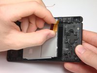
    • Lift the top LCD out of the plastic frame. Carefully thread the ribbon cable out of the hinge to avoid damaging it.

  23. Nintendo DSi Outer Casing Replacement: passo 23, immagine 1 di 1
    • To remove the speakers, place a flat object underneath and gently pry them off.

  24. Nintendo DSi Outer Casing Replacement, Outer Casing: passo 24, immagine 1 di 1
    • On the bottom cover, use a screwdriver to remove the 3 Phillips screws holding the battery compartment.

    • Removing the 2 lower screws also removes the "L" trigger.

    • The "L" trigger has a spring behind its center and a small metal axle in its joint.

  25. Nintendo DSi Outer Casing Replacement: passo 25, immagine 1 di 1
    • Use a small tool to pry the battery compartment off the bottom cover.

  26. Nintendo DSi Outer Casing Replacement: passo 26, immagine 1 di 1
    • Use a screwdriver to remove the 5 screws on the stylus holder.

    • Also disconnect and remove the "R" trigger button, which is held in place by two of the five stylus holder screws.

    • The "R" trigger has a spring behind its center and a small metal axle in its joint.

  27. Nintendo DSi Outer Casing Replacement: passo 27, immagine 1 di 1
    • Under the stylus holder is the SD card port.

    • Gently lift the SD card port off the bottom cover.

    • Remove the metal shield and flap from under the SD card port.

  28. Nintendo DSi Outer Casing Replacement: passo 28, immagine 1 di 1
    • This picture shows the LCD screen, battery compartment, and SD card slot (metal shield and flap) with bottom outer casing.

  29. Nintendo DSi Outer Casing Replacement: passo 29, immagine 1 di 1
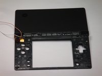
    • The complete DSi outer casing can now be replaced. Parts listed left to right: top cover, top LCD screen casing, touch LCD screen casing, and bottom cover.

    • Follow the guides for the replacement of the DSi components backwards with your new outer casing.

Conclusione

To reassemble your device, follow these instructions in reverse order.

Altre 2 persone hanno completato questa guida.

rjcamero

Membro da: 11/05/09

44 Reputazione

3 Guide realizzate

Team

Cal Poly, Team 6-1, Maness Fall 2009 Membro di Cal Poly, Team 6-1, Maness Fall 2009

CPSU-MANESS-F09S6G1

5 Membri

4 Guide realizzate

Un commento

Pictures are too dark to properly see where the structures mentioned in the text are, but worse than this, Steps 21 and 22 do not properly explain the “twist” method that you need to use with extreme caution! This is the Achille’s heel of dismantling the device and if you’re gonna make a mistake, let this not be the one…

Murat Kiymaz - Replica

Aggiungi Commento

Visualizza Statistiche:

Ultime 24 Ore: 7

Ultimi 7 Giorni: 43

Ultimi 30 Giorni: 150

Tutti i Tempi: 12,655