Salta al contenuto principale
Unisciti alla Community delle riparazioni - Crea un account

Depth Sensor Node Enclosure Assembly

Cosa ti serve

    1. Depth Sensor Node Enclosure Assembly, Running Node Builder Web App: passo 1, immagine 1 di 3 Depth Sensor Node Enclosure Assembly, Running Node Builder Web App: passo 1, immagine 2 di 3 Depth Sensor Node Enclosure Assembly, Running Node Builder Web App: passo 1, immagine 3 di 3
      • open Anaconda Navigator

      • launch Spyder

      • click 'Open File' and select "node_builder.py" under "\Documents\anvil"

      • click the 'Run' button

      • visit this link to get started: Node Builder

      Chiedi a FixBot

      Aggiungi Commento

    2. Depth Sensor Node Enclosure Assembly, Outside Structure: passo 2, immagine 1 di 3 Depth Sensor Node Enclosure Assembly, Outside Structure: passo 2, immagine 2 di 3 Depth Sensor Node Enclosure Assembly, Outside Structure: passo 2, immagine 3 di 3
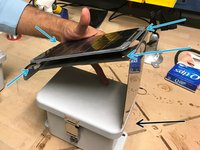
      • Obtain a solar panel with the appropriate metal plate.

      • Obtain the correctly bend metal plate.

      • The enclosure is the box where the sensor board, and wires are kept to protect from the environment.

      • Obtain the enclosure with the predrilled holes.

      Chiedi a FixBot

      Aggiungi Commento

    3. Depth Sensor Node Enclosure Assembly, Extending the Solar Panel Wire: passo 3, immagine 1 di 3 Depth Sensor Node Enclosure Assembly, Extending the Solar Panel Wire: passo 3, immagine 2 di 3 Depth Sensor Node Enclosure Assembly, Extending the Solar Panel Wire: passo 3, immagine 3 di 3
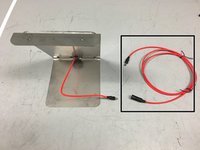
      • Obtain the solar panel extension cable

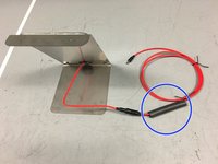
      • Obtain heat-shrink tubing and place it around the cable

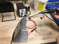
      • Cover the connection between the solar panel wire and the extension cable with the heat-shrink tubing. Then, use a heat gun to shrink the tubing, creating a water-tight seal around the connection

      Chiedi a FixBot

      Aggiungi Commento

    4. Depth Sensor Node Enclosure Assembly, Preparing Solar Panel Wire: passo 4, immagine 1 di 2 Depth Sensor Node Enclosure Assembly, Preparing Solar Panel Wire: passo 4, immagine 2 di 2
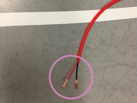
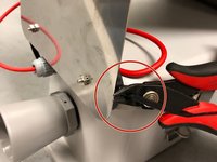
      • Trim the solar panel extension wire so there is approximately 20 inches of wire from the connection point

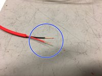
      • Strip the wires as shown in the image

      • Twist the ends of the wires

      Chiedi a FixBot

      Aggiungi Commento

    5. Depth Sensor Node Enclosure Assembly, Attaching The Solar Panel: passo 5, immagine 1 di 3 Depth Sensor Node Enclosure Assembly, Attaching The Solar Panel: passo 5, immagine 2 di 3 Depth Sensor Node Enclosure Assembly, Attaching The Solar Panel: passo 5, immagine 3 di 3
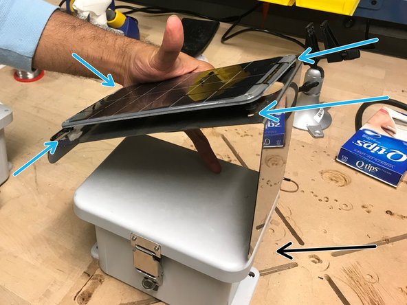
      • Attach the solar panel onto the metal plate.

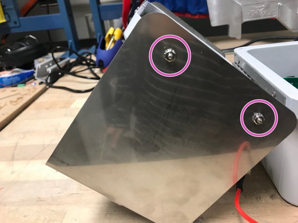
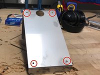
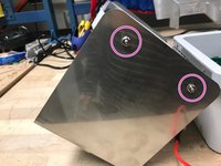
      • Using screws and a screw driver, screw the solar panel into these holes. Now that the solar panel is attached to the metal plate, attach the metal plate onto the lid of the enclosure

      • Note: the tall side of the metal plate should be on the same side of the enclosure as the holes for the ultrasonic sensor and cable glands.

      • The screws and nuts should be screwed in this matter in the holes on the sides of the box lid (meaning the nut is on the outside)

      Chiedi a FixBot

      Aggiungi Commento

    6. Depth Sensor Node Enclosure Assembly, Adding The Velcro: passo 6, immagine 1 di 2 Depth Sensor Node Enclosure Assembly, Adding The Velcro: passo 6, immagine 2 di 2
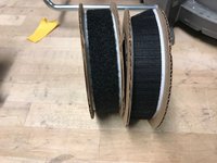
      • Obtain velcro

      • Add velcro with soft side inside the enclosure in the following places

      Chiedi a FixBot

      Aggiungi Commento

    7. Depth Sensor Node Enclosure Assembly, Solar Panel Wire: passo 7, immagine 1 di 3 Depth Sensor Node Enclosure Assembly, Solar Panel Wire: passo 7, immagine 2 di 3 Depth Sensor Node Enclosure Assembly, Solar Panel Wire: passo 7, immagine 3 di 3
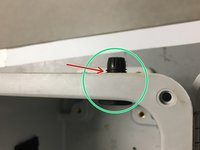
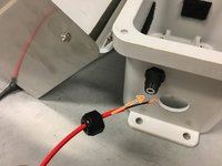
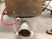
      • Now we need to insert the red extension wire from the solar panel into the enclosure box

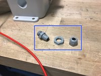
      • Obtain a cable gland

      • Screw the cable gland into the wall of the enclosure, through the small hole, as shown

      • Place an o-ring between the cable gland and outer-wall of the enclosure

      • Insert the solar panel extension wire into the cable gland as shown, leaving approximately 8 inches of wire inside the enclosure

      Chiedi a FixBot

      Aggiungi Commento

    8. Depth Sensor Node Enclosure Assembly, Solar Panel Wire Pt. 2: passo 8, immagine 1 di 2 Depth Sensor Node Enclosure Assembly, Solar Panel Wire Pt. 2: passo 8, immagine 2 di 2
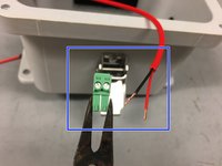
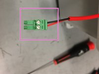
      • Obtain a plugable header and ensure the ends of the wires are twisted

      • Screw the wires into the plugable header as shown in the picture

      • Note: hand tight is just right.

      Chiedi a FixBot

      Aggiungi Commento

    9. Depth Sensor Node Enclosure Assembly, Depth Sensor Assembly: passo 9, immagine 1 di 3 Depth Sensor Node Enclosure Assembly, Depth Sensor Assembly: passo 9, immagine 2 di 3 Depth Sensor Node Enclosure Assembly, Depth Sensor Assembly: passo 9, immagine 3 di 3
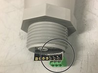
      • Solder a 3-prong terminal block to the ground, power, and data (#5) through-holes on the depth sensor

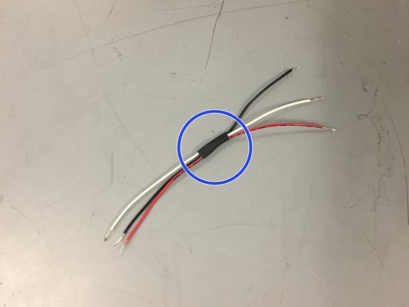
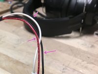
      • For organization, bind three wires (red, white, and black) with a small piece of shrink wrap

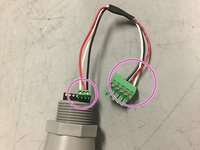
      • Connect the wires as shown in the picture (black to ground, red to power, white for data)

      Chiedi a FixBot

      Aggiungi Commento

    10. Depth Sensor Node Enclosure Assembly, Depth Sensor Installation: passo 10, immagine 1 di 3 Depth Sensor Node Enclosure Assembly, Depth Sensor Installation: passo 10, immagine 2 di 3 Depth Sensor Node Enclosure Assembly, Depth Sensor Installation: passo 10, immagine 3 di 3
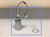
      • Assemble the depth sensor by adding the o-rings, and the connective wires in the order pictured, leaving the nut ring to the side

      • Note that the connective wires connect the depth sensor to the sensor node board. Remember, red wire is responsible for power, black is for ground, and white is for data

      • Place the depth sensor through the larger hole, and secure it firmly by tightening the nut ring

      • Make sure the nut ring is tightened securely as it will keep the enclosure water-tight

      Chiedi a FixBot

      Aggiungi Commento

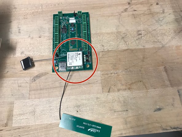
    11. Depth Sensor Node Enclosure Assembly, Attaching GPS and Antenna to Modem: passo 11, immagine 1 di 3 Depth Sensor Node Enclosure Assembly, Attaching GPS and Antenna to Modem: passo 11, immagine 2 di 3 Depth Sensor Node Enclosure Assembly, Attaching GPS and Antenna to Modem: passo 11, immagine 3 di 3
      • Obtain the cell module (modem), GPS, and antenna

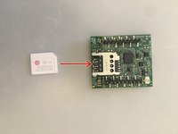
      • Insert Super SIM card into cell module

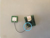
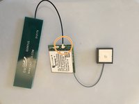
      • Attach the GPS to the connection shown (grey wire)

      • Attach the antenna to the connection shown (black wire)

      Chiedi a FixBot

      Aggiungi Commento

    12. Depth Sensor Node Enclosure Assembly, Adding Velcro to GPS and Antenna: passo 12, immagine 1 di 1
      • Attach rough-sided velcro on the antenna and GPS as shown in the picture.

      Chiedi a FixBot

      Aggiungi Commento

    13. Depth Sensor Node Enclosure Assembly, Adding Velcro and Block Plug  to Battery: passo 13, immagine 1 di 3 Depth Sensor Node Enclosure Assembly, Adding Velcro and Block Plug  to Battery: passo 13, immagine 2 di 3 Depth Sensor Node Enclosure Assembly, Adding Velcro and Block Plug  to Battery: passo 13, immagine 3 di 3
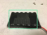
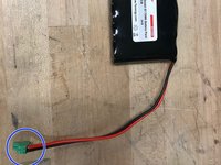
      • Obtain velcro and lithium ion 3.7V battery. Attach rough side of velcro on battery

      • Be very careful not to short the battery by touching the two wires together.

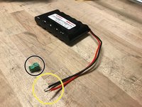
      • Obtain a block plug.

      • Twist the wires of the battery so they fit nicely in the plugable-header block

      • Screw the wires into the block plug

      • Note: hand tight is just right.

      Chiedi a FixBot

      Aggiungi Commento

    14. Depth Sensor Node Enclosure Assembly, Preparing Battery for Enclosure: passo 14, immagine 1 di 3 Depth Sensor Node Enclosure Assembly, Preparing Battery for Enclosure: passo 14, immagine 2 di 3 Depth Sensor Node Enclosure Assembly, Preparing Battery for Enclosure: passo 14, immagine 3 di 3
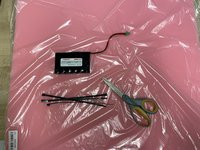
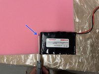
      • Obtain one battery, 4 zip ties, foam, and a pair of scissors

      • Cut out two battery-sized pieces of foam

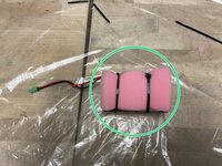
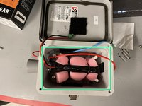
      • Sandwich the battery between the two pieces of foam and secure it using the zip-ties. Connect the zip-ties to make two extra long zip-ties

      Chiedi a FixBot

      Aggiungi Commento

    15. Depth Sensor Node Enclosure Assembly, Adding Standoffs and Battery to Enclosure: passo 15, immagine 1 di 3 Depth Sensor Node Enclosure Assembly, Adding Standoffs and Battery to Enclosure: passo 15, immagine 2 di 3 Depth Sensor Node Enclosure Assembly, Adding Standoffs and Battery to Enclosure: passo 15, immagine 3 di 3
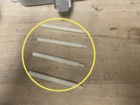
      • Obtain eight 1.5-inch long standoffs. Screw the standoffs together as shown, to make four 3-inch long standoffs

      • Screw the standoffs into the enclosure

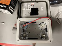
      • Insert battery into the enclosure. Make sure the wire is on the sensor-side of the enclosure

      Chiedi a FixBot

      Aggiungi Commento

    16. Depth Sensor Node Enclosure Assembly, Connecting Jumpers, SD card, and Modem on Sensor Node Board: passo 16, immagine 1 di 3 Depth Sensor Node Enclosure Assembly, Connecting Jumpers, SD card, and Modem on Sensor Node Board: passo 16, immagine 2 di 3 Depth Sensor Node Enclosure Assembly, Connecting Jumpers, SD card, and Modem on Sensor Node Board: passo 16, immagine 3 di 3
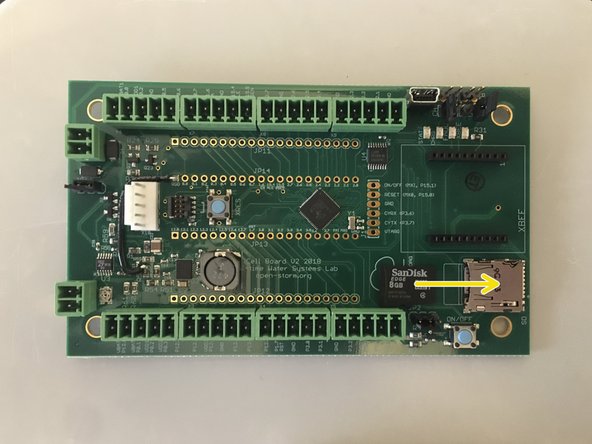
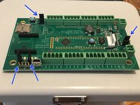
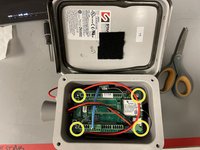
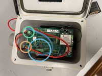
      • Obtain Open-Storm board and place 4 jumpers in the spots shown

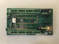
      • Insert microSD card into board

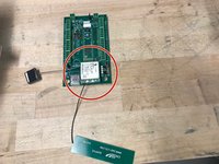
      • Attach the cellular module onto the sensor node board in the appropriate place

      Chiedi a FixBot

      Aggiungi Commento

    17. Depth Sensor Node Enclosure Assembly, Connecting Sensors, Solar Panel to Node Board: passo 17, immagine 1 di 2 Depth Sensor Node Enclosure Assembly, Connecting Sensors, Solar Panel to Node Board: passo 17, immagine 2 di 2
      • Put the board on top of the standoffs in the enclosure, and screw it in using a screw driver

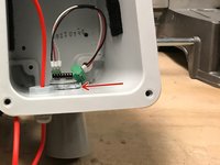
      • Connect the depth sensor wire as shown

      • Connect the solar panel wire to the board as shown

      • Connect the battery wire to the board as shown

      Chiedi a FixBot

      Aggiungi Commento

    18. Depth Sensor Node Enclosure Assembly, Securing Antenna, GPS, and Battery: passo 18, immagine 1 di 1
      • Attach the antenna, and the GPS on the velcro to the closest wall on the inside of the enclosure

      Chiedi a FixBot

      Aggiungi Commento

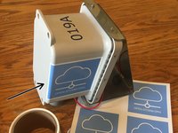
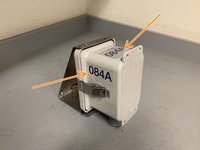
    19. Depth Sensor Node Enclosure Assembly, Applying Open-Storm and Node ID stickers: passo 19, immagine 1 di 3 Depth Sensor Node Enclosure Assembly, Applying Open-Storm and Node ID stickers: passo 19, immagine 2 di 3 Depth Sensor Node Enclosure Assembly, Applying Open-Storm and Node ID stickers: passo 19, immagine 3 di 3
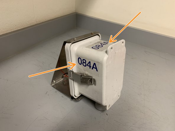
      • apply the open-storm sticker to the side of the enclosure as shown

      • apply the unique node ID sticker to the two spots shown

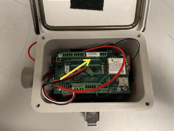
      • print a label with the unique node ID that appears on the sticker using the label maker

      • apply the label to the board as shown

      Chiedi a FixBot

      Aggiungi Commento

    20. Depth Sensor Node Enclosure Assembly, Securing the Solar Panel Wire: passo 20, immagine 1 di 3 Depth Sensor Node Enclosure Assembly, Securing the Solar Panel Wire: passo 20, immagine 2 di 3 Depth Sensor Node Enclosure Assembly, Securing the Solar Panel Wire: passo 20, immagine 3 di 3
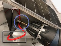
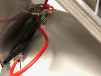
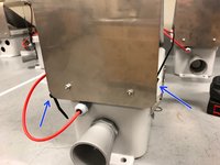
      • Fold wire over itself so that the portion above the hose clamp won't have slack when the black wire section is pressed against the inside of the panel

      • Obtain a hose clamp, and secure the red part of the wire to the black section using a drill fitted with the drill bit

      • Wrap a zip tie around the wire as shown.

      • Use a second zip tie to connect the ends of the first one

      Chiedi a FixBot

      Aggiungi Commento

    21. Depth Sensor Node Enclosure Assembly, Securing the Solar Panel Wire-continued: passo 21, immagine 1 di 3 Depth Sensor Node Enclosure Assembly, Securing the Solar Panel Wire-continued: passo 21, immagine 2 di 3 Depth Sensor Node Enclosure Assembly, Securing the Solar Panel Wire-continued: passo 21, immagine 3 di 3
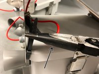
      • Use a clamp to tighten the zip tie

      • Position each zip tie head as shown while tightening

      • Clip excess zip tie as close as possible

      Chiedi a FixBot

      Aggiungi Commento

    22. Depth Sensor Node Enclosure Assembly, Adjusting Solar Charger Potentiometer: passo 22, immagine 1 di 3 Depth Sensor Node Enclosure Assembly, Adjusting Solar Charger Potentiometer: passo 22, immagine 2 di 3 Depth Sensor Node Enclosure Assembly, Adjusting Solar Charger Potentiometer: passo 22, immagine 3 di 3
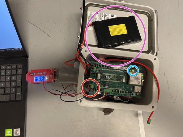
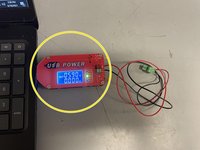
      • Obtain USB power supply, plug into a laptop, and set output to 5.9V

      • Check the voltage with a voltmeter (you may have to set the power supply to ~5.8V for the voltmeter to read 5.9V)

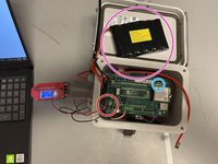
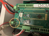
      • Plug in the green terminal block from the power supply into the Open-Storm board solar port.

      • Confirm the solar charge LED is off.

      • Plug in a dead battery to the battery port. This step will not work with a charged battery

      • CAREFULLY turn the silver potentiometer next to the charge controller IC with a small flathead screw driver until the charge light turns on.

      • Although the screw has a phillip screw head, using a phillip screwdriver may damage the potentiometer. The hole in the center is too shallow for most screwdrivers. It is easier to use a flathead screwdriver!

      • Resource: 1. How to Select MPP Voltage on a Solar Charge Controller 2. Sunny Buddy Solar Charger V13 Hookup Guide

      Chiedi a FixBot

      Aggiungi Commento

    23. Depth Sensor Node Enclosure Assembly, Preparing Lock: passo 23, immagine 1 di 3 Depth Sensor Node Enclosure Assembly, Preparing Lock: passo 23, immagine 2 di 3 Depth Sensor Node Enclosure Assembly, Preparing Lock: passo 23, immagine 3 di 3
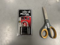
      • obtain a master lock and a pair of scissors

      • cut the lock and key out of the packaging

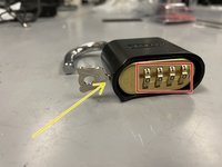
      • set the lock to the default combination, 0-0-0-0, open the lock

      • put the key into the lock and twist clockwise 90 degrees

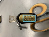
      • while the key is still twisted, set the combo to 2-2-4-5

      • remove the key, and the lock is ready to go

      Chiedi a FixBot

      Aggiungi Commento

    24. Depth Sensor Node Enclosure Assembly, Preparing Node Handle pt. 1: passo 24, immagine 1 di 3 Depth Sensor Node Enclosure Assembly, Preparing Node Handle pt. 1: passo 24, immagine 2 di 3 Depth Sensor Node Enclosure Assembly, Preparing Node Handle pt. 1: passo 24, immagine 3 di 3
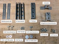
      • obtain the materials in the quantities shown

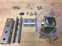
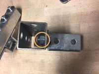
      • screw the U-bracket onto one of the 8" strut channels, using one of the 1/2" hex bolts and the 1/2" strut channel nut

      • attach the remaining 8" strut channel piece to the U-bracket, using two 1/2" hex bolts and two 1/2" hex nuts

      • be sure not to center the strut channel you are attaching the the U-bracket, instead make one side of the U-bracket flush with end of the strut channel (as shown)

      Chiedi a FixBot

      Aggiungi Commento

    25. Depth Sensor Node Enclosure Assembly, Preparing Node Handle pt. 2: passo 25, immagine 1 di 1
      • insert the two 5/16" strut channel nuts into the back of the horizontal strut channel as shown

      Chiedi a FixBot

      Aggiungi Commento

    26. Depth Sensor Node Enclosure Assembly, Preparing Node Handle pt. 3: passo 26, immagine 1 di 3 Depth Sensor Node Enclosure Assembly, Preparing Node Handle pt. 3: passo 26, immagine 2 di 3 Depth Sensor Node Enclosure Assembly, Preparing Node Handle pt. 3: passo 26, immagine 3 di 3
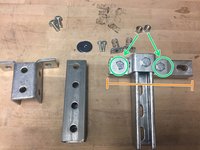
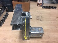
      • attach the winged strut channel bracket to the 8" telespar using the remaining two hex bolts and hex nuts

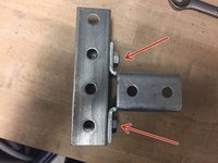
      • when tightening the hex nuts, ensure the edge of the nut points directly outwards (as shown), or else the struct channel piece will not slide inside

      • confirm the T-shaped strut channel piece slides into the telespar, and the handle is now finished

      Chiedi a FixBot

      Aggiungi Commento

    27. Depth Sensor Node Enclosure Assembly, Adding Reinforcement Rails: passo 27, immagine 1 di 2 Depth Sensor Node Enclosure Assembly, Adding Reinforcement Rails: passo 27, immagine 2 di 2
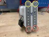
      • Attach the reinforcement rails to the back of the node using two 5/16" hex bolts, two 5/16" hex bolts, and two 5/16" 1.25" OD washers. Insert the bolts the bottom two holes of the node enclosure, using the bottom holes of the rails as shown in the image.

      • Line up the top holes of the rails with the top node enclosure holes and then tighten the bottom bolts.

      Chiedi a FixBot

      Aggiungi Commento

    28. Depth Sensor Node Enclosure Assembly, Attaching Enclosure to Handle: passo 28, immagine 1 di 3 Depth Sensor Node Enclosure Assembly, Attaching Enclosure to Handle: passo 28, immagine 2 di 3 Depth Sensor Node Enclosure Assembly, Attaching Enclosure to Handle: passo 28, immagine 3 di 3
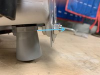
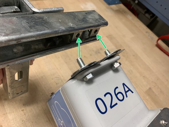
      • screw the node enclosure onto the strut channel using the two 5/16" hex bolts and two 5/16" 1.5"OD washers. Be sure to put bolts through the reinforcement rails.

      • removing the T-shaped strut channel piece from the telespar makes this step easier

      • slide the T-shaped piece back into the telespar

      Chiedi a FixBot

      Aggiungi Commento

    29. Depth Sensor Node Enclosure Assembly, Finishing Touches: passo 29, immagine 1 di 3 Depth Sensor Node Enclosure Assembly, Finishing Touches: passo 29, immagine 2 di 3 Depth Sensor Node Enclosure Assembly, Finishing Touches: passo 29, immagine 3 di 3
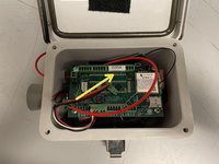
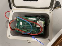
      • this is what the node should look like on the inside

      • make sure the battery is plugged in

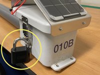
      • attach the lock to the outside of the enclosure

      • return to Node Builder for instructions on how to drop off the node at the testing rack

      Chiedi a FixBot

      Aggiungi Commento

Linea Traguardo

Annulla: non ho completato questa guida.

Altre 3 persone hanno completato questa guida.

Brooke Mason

Membro da: 05/29/19

2.958 Reputazione

17 guide realizzate

Team

Open-Storm Membro di Open-Storm

Community

14 Membri

48 guide realizzate

0Commenti sulla guida

Aggiungi Commento

Visualizza statistiche:

Ultime 24 ore: 1

Ultimi 7 giorni: 8

Ultimi 30 giorni: 23

Tutti i Tempi: 1,541