Questa versione può contenere modifiche errate. Passa all'ultima istantanea verificata.
Cosa ti serve
-
-
Per costruire uno strumento di carica per condensatori, devi prima prendere i giusti materiali. Questi comprendono:
-
Due cavi. I requisiti minimi sono 12AWG e 600 V, certificati per grandi condensatori elettrolitici usati in alimentatori, circuiti di avvio di motori elettrici e circuiti per il flash delle fotocamere.
-
Una resistenza certificata per dissipare il calore generato dalla scarica del condensatore. I requisiti minimi sono 2k Ohm e 5 W per piccoli condensatori, 20k Ohm e 5 W per grandi condensatori elettrolitici usati in alimentatori, circuiti di avvio di motori elettrici e circuiti per il flash delle fotocamere.
-
Guaina termorestringente.
-
-
-
Infila il cavo in una porzione di guaina termorestringente, assicurandoti di coprire completamente la saldatura e ogni parte conduttiva del cavo o della resistenza.
-
Usa una pistola termica o un accendino per restringere la guaina sulla saldatura, assicurandoti che non venga esposta alcuna parte conduttiva.
-
-
-
Questo passaggio è privo di traduzione. Aiuta a tradurlo
-
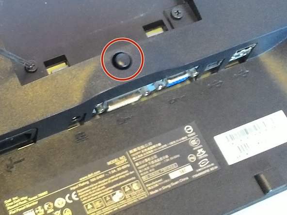
Before replacing the capacitors, open the monitor and find the power board. First, remove the monitor from the stand.
-
The button to remove the stand is located on the back of the monitor, above the ports.
-
-
Questo passaggio è privo di traduzione. Aiuta a tradurlo
-
Remove the 4 black screws on the back of the monitor. This detaches the screen and housing from the case internally.
-
-
Questo passaggio è privo di traduzione. Aiuta a tradurlo
-
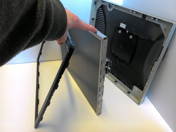
Flip the monitor around and locate the two slots on the edges. These slots are below the screen where the faceplate is attached.
-
Use a flat tool (such as a flathead screwdriver) to pop the front frame off. It is attached via plastic snaplocks and will come off with some prying.
-
Once the faceplate is removed, the monitor can be removed from the housing, leaving the monitor and the faceplate attached with a ribbon wire. The wire can now be pulled from the slot, fully removing the faceplate from the monitor.
-
-
Questo passaggio è privo di traduzione. Aiuta a tradurlo
-
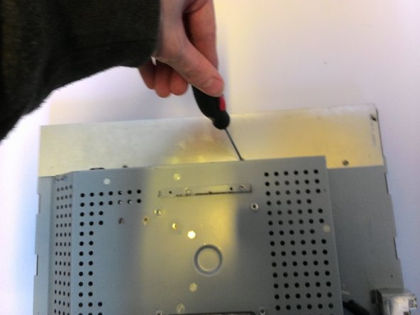
Remove the plates protecting the wires. There are a total of 5 screws holding two plates onto the top and bottom.
-
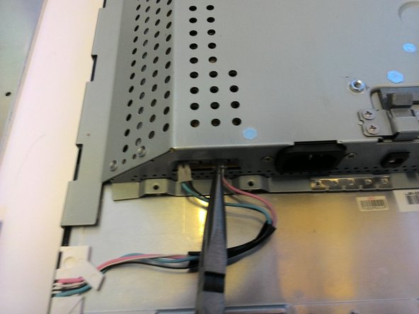
With the plates removed, we can now unplug the 2 green and 2 pink wires connecting the electronics to the screen. This is best done with needle nose pliers, since the attaching head must be depressed and pulled at the same time.
-
-
Questo passaggio è privo di traduzione. Aiuta a tradurlo
-
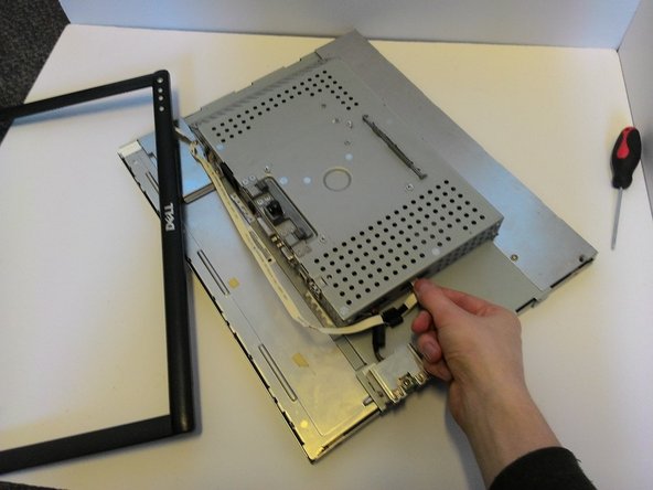
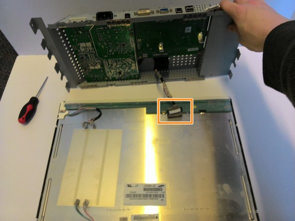
Remove the 4 screws on the sides (two on each side) to detach the electronics housing from the screen.
-
Carefully lifting the housing off the screen, find and unlock the ribbon wire, then unplug it.
-
-
Questo passaggio è privo di traduzione. Aiuta a tradurlo
-
Making sure to only be touching the rubber handle of a screwdriver or another tool with a rubber grip, connect each set of capacitor leads with the metal of the tool. This may cause sparks or pops. Ensure every single possible capacitor is discharged before proceeding!
-
-
Questo passaggio è privo di traduzione. Aiuta a tradurlo
-
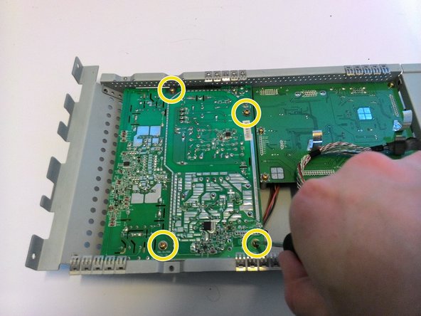
After all the capacitors are safely discharged, flip the housing over and remove the three indicated screws from the back.
-
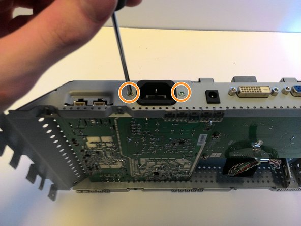
Flip it onto its side and remove the two screws attaching the powerboard to the power port.
-
Remove the four screws from the powerboard itself. This frees the powerboard from the housing.
-
-
Questo passaggio è privo di traduzione. Aiuta a tradurlo
-
Now you can remove and manipulate the circuit board.
-
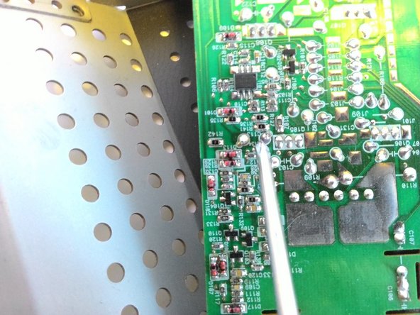
Locate any capacitors that are blown. The tops will be rounded rather than flat or could have dried orange fluid spilling from the tops. These need to be replaced. Identify their capacitance and voltage and remember these.
-
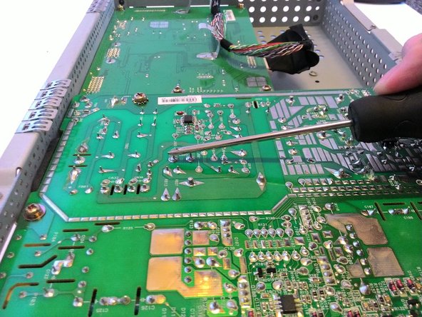
Using a soldering iron and desoldering tape, remove the solder attaching any blown capacitors.
-
-
Questo passaggio è privo di traduzione. Aiuta a tradurlo
-
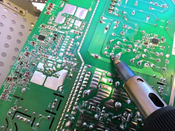
Insert the new capacitors, ensuring that the negative is on the proper side via observing the capacitor and the board.
-
Solder the new capacitors into the board.
-


Annulla: non ho completato questa guida.
Altre 4 persone hanno completato questa guida.

Team

Michigan Tech, Team 1-4, Lauer Spring 2016 Membro di Michigan Tech, Team 1-4, Lauer Spring 2016
MTU-LAUER-S16S1G4
1 Membro
3 Guide realizzate
Un commento
I seem to have a different board layout inside my DELL 1905FP. Maybe they differ internationally because of the built-in transformator.
Found and replaced the faulty capacitors on the transformator board. It is aliiiive :)
Thanks for the guide. Opening the case from the front frame first was the trick, I was looking for.