Salta al contenuto principale
Unisciti alla Community delle riparazioni - Crea un account

Accessing Logicboard

Cosa ti serve

    1. Accessing Logicboard, Front and Back Cover: passo 1, immagine 1 di 2 Accessing Logicboard, Front and Back Cover: passo 1, immagine 2 di 2
      • Remove the following screws:

      • Two silver 3.15mm Phillips #00 screws on the right side of the camera

      • Two silver 2.08mm Phillips #00 screws on the left side of the camera

      Chiedi a FixBot

      Aggiungi Commento

    2. Accessing Logicboard: passo 2, immagine 1 di 1
      • Remove the two indicated screws on the bottom of the camera:

      • The screw circled in red is a longer silver 3.15mm Phillips #00 screw

      • The screw circled in blue is a shorter silver 2.25mm Phillips #00 screw

      Chiedi a FixBot

      Aggiungi Commento

    3. Accessing Logicboard: passo 3, immagine 1 di 2 Accessing Logicboard: passo 3, immagine 2 di 2
      • Carefully pull the back of casing away from the front.

      Chiedi a FixBot

      Aggiungi Commento

    4. Accessing Logicboard: passo 4, immagine 1 di 3 Accessing Logicboard: passo 4, immagine 2 di 3 Accessing Logicboard: passo 4, immagine 3 di 3
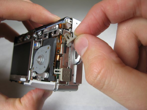
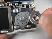
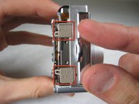
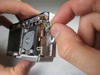
      • After removing the back cover, several things must be removed.

      • Silver donut-shaped button will fall off. Place separately. Remove the plug covers on the right side of camera, labeled “PC/AV” and “DC IN 4.5V”.

      Chiedi a FixBot

      Aggiungi Commento

    5. Accessing Logicboard: passo 5, immagine 1 di 2 Accessing Logicboard: passo 5, immagine 2 di 2
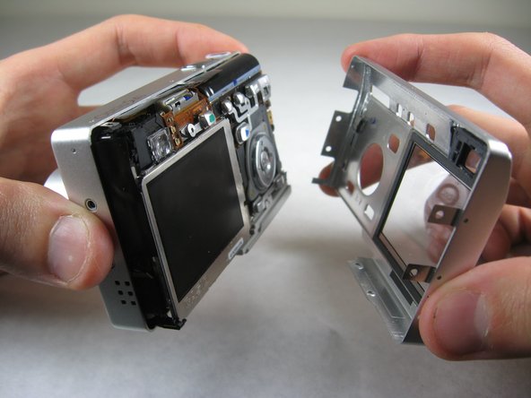
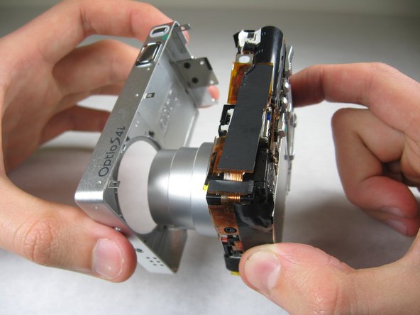
      • To remove the front cover, gently hold the inside structure of the camera and slowly pull the front cover off.

      Chiedi a FixBot

      Aggiungi Commento

    1. Accessing Logicboard, Logicboard: passo 6, immagine 1 di 2 Accessing Logicboard, Logicboard: passo 6, immagine 2 di 2
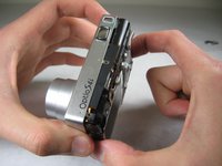
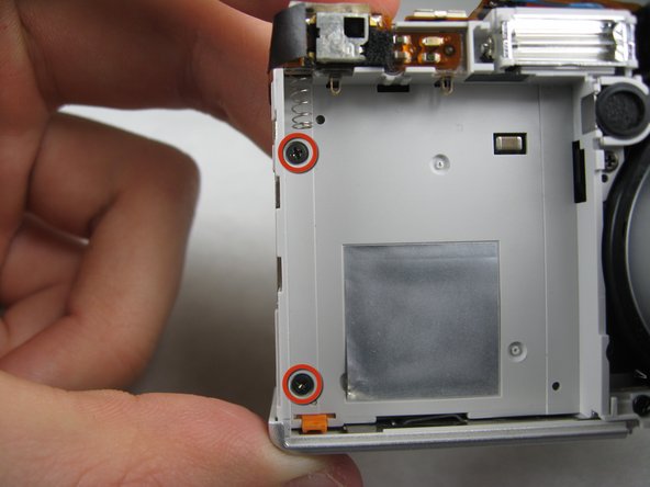
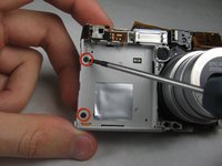
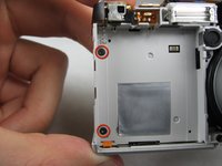
      • On the front of the camera, in battery case, remove screws indicated:

      • Two black 2.05mm Phillips #00 screws

      Chiedi a FixBot

      Aggiungi Commento

    2. Accessing Logicboard: passo 7, immagine 1 di 2 Accessing Logicboard: passo 7, immagine 2 di 2
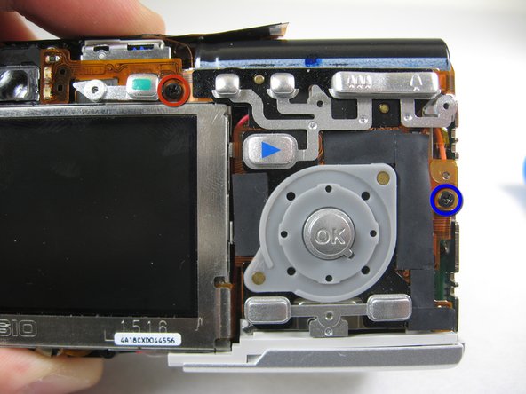
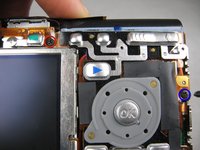
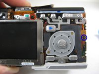
      • Flip the camera over to the backside and remove screws indicated:

      • The screw circled in red is a longer black 3.00mm Phillips #00 screw

      • The screw circled in blue is a shorter black 2.00mm Phillips #00 screw

      Chiedi a FixBot

      Aggiungi Commento

    3. Accessing Logicboard: passo 8, immagine 1 di 1
      • Pull the cover plate off for the two power cord jacks.

      Chiedi a FixBot

      Aggiungi Commento

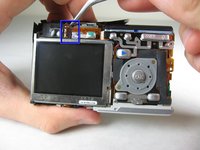
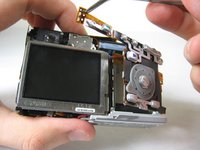
    4. Accessing Logicboard: passo 9, immagine 1 di 3 Accessing Logicboard: passo 9, immagine 2 di 3 Accessing Logicboard: passo 9, immagine 3 di 3
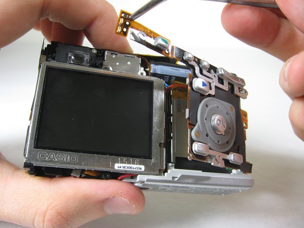
      • Cautiously and gently pull up the control board at the upper left corner, next to the viewfinder.

      Chiedi a FixBot

      Aggiungi Commento

    5. Accessing Logicboard: passo 10, immagine 1 di 1
      • Remove the orange tape on top of the SD cardholder.

      Chiedi a FixBot

      Aggiungi Commento

    6. Accessing Logicboard: passo 11, immagine 1 di 1
      • Open the battery cover.

      Chiedi a FixBot

      Aggiungi Commento

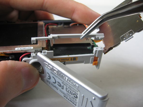
    7. Accessing Logicboard: passo 12, immagine 1 di 2 Accessing Logicboard: passo 12, immagine 2 di 2
      • Lift the indicated plastic piece off.

      Chiedi a FixBot

      Aggiungi Commento

    8. Accessing Logicboard: passo 13, immagine 1 di 2 Accessing Logicboard: passo 13, immagine 2 di 2
      • Remove screws indicated:

      • Two black 4.80mm Phillips #00 screws

      Chiedi a FixBot

      Aggiungi Commento

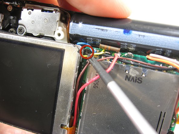
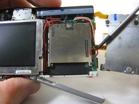
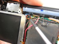
    9. Accessing Logicboard: passo 14, immagine 1 di 1
      • Unsolder points indicated.

      • Please refer to steps 1 through 6 of the Ifixit soldering guide to unsolder these leads.

      Chiedi a FixBot

      Aggiungi Commento

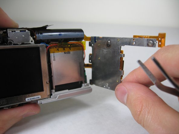
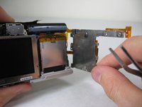
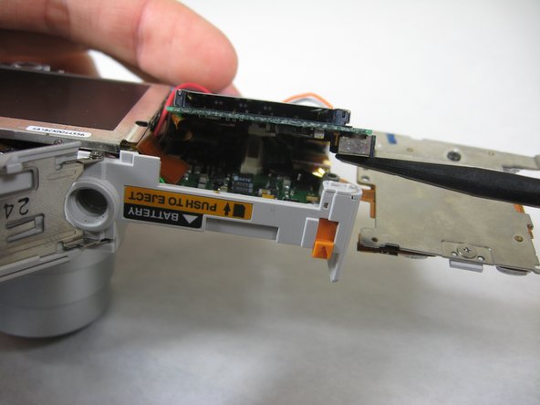
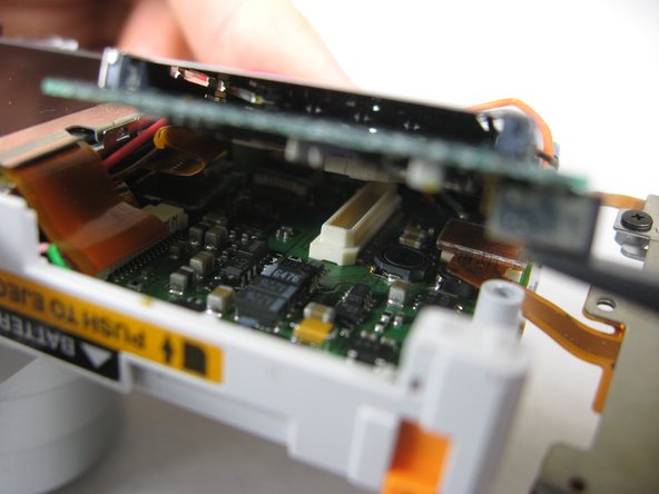
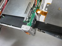
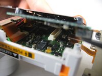
    10. Accessing Logicboard: passo 15, immagine 1 di 3 Accessing Logicboard: passo 15, immagine 2 di 3 Accessing Logicboard: passo 15, immagine 3 di 3
      • Carefully lift up SD cardholder to reveal logicboard.

      Chiedi a FixBot

      Aggiungi Commento

Conclusione

To reassemble your device, follow these instructions in reverse order.

Annulla: non ho completato questa guida.

Nicole Wong

Membro da: 01/30/11

371 Reputazione

3 guide realizzate

Team

Cal Poly, Team 4-29, Regan Winter 2011 Membro di Cal Poly, Team 4-29, Regan Winter 2011

CPSU-REGAN-W11S4G29

3 Membri

10 guide realizzate

0Commenti sulla guida

Aggiungi Commento

Visualizza statistiche:

Ultime 24 ore: 4

Ultimi 7 giorni: 11

Ultimi 30 giorni: 39

Tutti i Tempi: 1,995