Introduzione
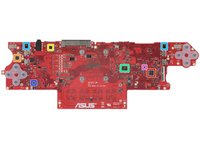
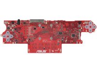
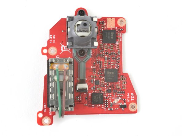
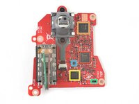
Identificazione dei chip per la console portatile Asus ROG Ally.
Dai un'occhiata al nostro smontaggio dell'Asus ROG Ally per ulteriori dettagli.
Molte grazie al membro della nostra community CChin per i suoi contributi!
Panoramica video
-
-
-
Processore applicativo octa-core AMD 100-000001278 Ryzen Z1 Extreme da 3,3 GHz
-
Memoria SDRAM LPDDR5 Samsung K3LKBKB0BM-MGCP da 4 GB
-
Caricabatterie buck-boost SMBus agli ioni di litio Renesas ISL9241HRTZ
-
Memoria EEPROM seriale onsemi CAT24C512 da 64 KB
-
Codec audio Realtek ALC3288
-
Amplificatore audio Cirrus Logic CS35L51X
-
Controller multifase Monolithic Power Systems MP2845A
 Chiedi a FixBot
-
-
-
Stadio di potenza da 45 A Monolithic Power Systems MP86949
-
Controller duale step-down sincrono con LDO Texas Instruments TPS51285ARUK
-
Regolatore step-down sincrono da 8 A Silergy SY8388ARHC
-
Convertitore step-down sincrono Silergy (probabile)
-
Convertitore DC-DC Monolithic Power Systems (probabile)
-
Regolatore LDO da 300 mA / 3,00 V Torex Semiconductor XC6223K3019R-G
-
Interruttore analogico SPDT a 2 canali Texas Instruments TMUX154ERSWR
-
-
-
Interruttore di carico VBUS USB KTS1690AEGAA-TA di Kinetic Technologies
-
Protezione da sovratensione da 4 A KTS1681AEUZ-TR di Kinetic Technologies
-
Interruttore di carico a doppia uscita con OVP di Kinetic Technologies ?
-
-
-
-
Accelerometro e giroscopio MEMS a 6 assi Bosch Sensortec BMI323 con sensore della temperatura
-
Probabile sensore della temperatura Texas Instruments
-
-
-
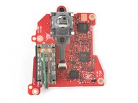
Controller integrato e per tastiera ITE Tech IT5125VG-192
-
Controller USB Type-C Power Delivery ITE Tech IT8856FN
-
Controller lettore schede Genesys Logic GL9755
-
Memoria flash di autenticazione da 32 MB Winbond W74M25JW
-
Microfono MEMS
-
Convertitore A/D a 15 canali e 8 bit ANPEC Electronics APL6012
-
Array a segnale misto Renesas (probabilmente)
-
-
-
Stadio di potenza da 30 A Monolithic Power Systems MP86903C
-
Regolatore buck sincrono DC-DC da 3 A Infineon IR3883MTRPBF
-
Regolatore LDO da 3 A / reg. (probabile) Global Mixed-mode Technology G9661M
-
Interruttore di carico da 6 A Texas Instruments TPS22975DSG
-
Interruttore di distribuzione di potenza uPI Semi uP9030Q (probabile)
-
Interruttore analogico SPST a 1 canale Texas Instruments TS5A3166DCKR
-
Porta AND singola a 2 ingressi Texas Instruments SN74LVC1G08
-
-
-
Probabile sensore della temperatura Texas Instruments
-
-
-
Probabilmente controller integrato ITE Tech IT8237FN248A
-
Probabilmente controller integrato ITE Tech IT8237FN120A
-
Convertitore A/D SG Micro SGM5200 a 16 canali, 12 bit, 1 MSPS
-
Riferimento di tensione SG Micro SGM4040B-2.5 da 2,5 V
-
Possibilmente driver aptico Awinic AW86223
-
-




11Commenti sulla guida
My Ally came with MediaTek MT7922 (RZ616). Since it has apparent issues with keeping a connection (not caused by the signal!) - I ordered an Intel AX210 to replace it, only to find out that it's apparently soldered and can't be replaced. This should have been mentioned by ifixit - definitely a bad decision! same for the soldered 16GB RAM. Another bad decision. Now I don't know what to do with the Ally. Unreliable Wifi is no option, so maybe return it..
When I wanted to update the BIOS, my console stopped turning on so now it is necessary to reprogram this BIOS but I can't find the file on the web, could you help me with a copy of your BIOS, I would be very grateful. To make a copy of the BIOS you could use the CH341 programmer
