Questa traduzione potrebbe non riflettere gli aggiornamenti più recenti dalla guida originale. Aiuta ad aggiornare la traduzione o visualizza la guida d'origine.
Introduzione
Utilizzare questa guida per sostituire completamente l'unità ottica. La sostituzione della scheda logica richiede la rimozione della scheda logica, oltre che della maggior parte degli altri componenti del Mac mini. Inoltre, la reinstallazione dei sensori termici potrebbe richiedere l'utilizzo di mastice.
Cosa ti serve
-
-
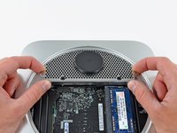
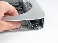
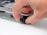
Posizionare i pollici negli incavi tagliati nel coperchio inferiore.
-
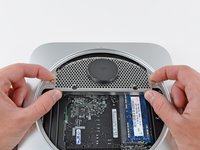
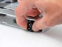
Ruotare il coperchio inferiore in senso antiorario finché il puntino bianco dipinto su di esso non è allineato con il cerchio in rilievo sul case esterno.
-
-
-
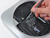
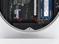
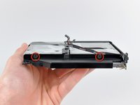
Rimuovere le due viti Torx T6 da 11,3 mm che fissano la ventola alla scheda logica, in prossimità della piastra dell'antenna.
There are actually 3 T6 screws securing the fan. The third screw is out of the screenshot, just below the RAM.
Nope, that third screw is actually just a post that the rubber grommet attached to the fan body slips over. Step 4 shows how the fan comes off of it. When you go to remove the fan, you simply remove the two screws closest to the antenna plate and then lift the fan off this post. The screw you are talking about is removed in Step 14 and does not need to be removed until this point.
Successful install completed, but I had some trouble getting the fan reinstalled. When I removed the fan from the "Step 14" post, the rubber piece stayed on the post. When attempting to reinstall the fan, it was impossible to get the loop to go back over that rubber piece. So, I had to remove the post (again), and with the help of the spudger and some patience, worked it through. Then installed the fan using the 2 screws and the post. I think it may have saved some time and trouble if I just removed all 3 in the first place, leaving the post in the fan.
meag -
On mine I needed to remove the 26 mm T6 Torx standoff during this step rather than step 12
on my mid-2011 mac mini, that 3rd T6 post/screw had to be removed to get the fan out. It goes right through a hole in the fan housing. No way the grommet is slipping over anything without wreaking major havoc.
-
-
-
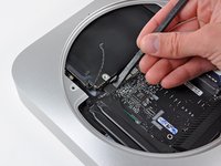
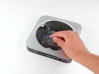
Sollevare la linguetta della ventola più vicina alla memoria RAM più vicina al distanziatore fissato al case esterno.
Pulling on the ear didn't do anything, so I removed the whole screw at this step. The screw stayed fixed on the fan and I didn't have to remove it at the step where you remove the logic board screws.
Probably I didn't want to use too much force .. but it worked
This is the approach I used. no way was the "ear" pulling over the head of the standoff without breaking something. The standoff simply unscrewed from whatever is under the logic board and stayed with the fan assembly. WAY safe
Loosen the fan standoff from the motherboard using a T6 driver.
When I pulled the fan ear off the standoff the rubber grommet stayed on the standoff. That's fine, but it makes it difficult to put the fan ear back on during reassembly. So I just pulled the rubber grommet off the standoff and put it into the hole in the fan ear. Then I was able to push the fan ear onto the standoff with out trouble during reassembly.
-
-
-
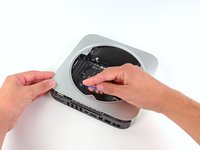
Sollevare la ventola dal Mac mini affinché sia possibile accedere al connettore.
-
Tirare con attenzione i cavi della ventola verso l'alto, per sollevare il connettore dal connettore femmina sulla scheda logica.
-
Rimuovere la ventola.
Be careful here, this is not a simple action. Pulling on the wires risks them coming out of the sockets of the connector that attaches to the pins on the board. I had to use an Xacto knife to push on the end of the connector to push it off the pins rather than pull.
Actually, just sliding a spudger under the wires and edging upwards is the easiest way to disconnect this connector - and most others, too.
-
-
-
Rimuovere la vite T6 da 3,5 mm che fissa la mascherina al dissipatore.
-
-
-
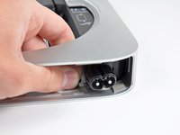
Sollevare la mascherina dall'estremità più vicina alla piastra dell'antenna.
-
Ruotare la mascherina fuori dal case esterno e rimuoverla dal Mac mini.
This is wrong step. If you need remove this out, it would be better to pull out logic board, and remember to remove cables attached on it before pull out.
-
-
-
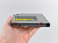
Rimuovere le viti seguenti, che fissano la piastra dell'antenna al Mac mini:
-
Due viti Torx T8 da 6,6 mm
-
Due viti Torx T8 da 5 mm o viti esagonali da 2 mm (vanno bene entrambi i cacciaviti)
The red circled screws are T9 in my Mac mini (not T8).
ditto here - the 6.6 mm screws that anchor to the HD (now SSD) are T9
I have tried several times but I have been unable to get all four holes to line up when replacing the antenna plate. I can get the two closer to the center of the mini just fine but no matter how I align the plate, one of the screws closer to the edge of the mini will be so far out of alignment that I cannot get the screw to go in. I had to leave one screw uninstalled. The plate is not distorted in any way. It is installed the same way it was before I removed, as far as I can tell. I am baffled! Has anyone been through this?
Galvanic, it pops in.
bkbkbk -
I had a really hard time with this. I was able to resolve it though: secure the other three screws first. Then I pushed my precision screwdriver into the hole and levered the wayward tab into position: it wedged in with an audible snap sound! Then I was able to fasten the final screw.
I have trouble with this step every time I repair one of these minis. Aaron, your tip worked perfectly for me, thanks. -Anne
The antenna plate assembly is a tongue and groove type. The plate has a "groove" and the rim of the outer case is the "lip". You have to slide it in and align the parts ant it fits perfectly .
jvilella -
To solve this, just pick on the plate on the semi circle side and with the tool "open" just slighter the space where the semicircle have to fit
Pedro -
Had the same problem - the reason was the replacement drive I used - it is thinner than the original one. So I could not get the far side of the drive correctly into the holes for the notches mounted on the drive; that is - the drive was always a little bit too far to the center of the mac case. Everything works fine until you try to install all four screws.
I found a simple solution: I attached some adhesive tape temporarily to the drive cover. By pulling on the tape while pushing the drive in its space the notches slipped into their holes. After this installing the antenna was no problem any more.
The key to this is to use needle-nose pliers to grasp the grate between the black plastic circle and the edge of the mini's case, and pull upwards (away from the hard drive beneath it). It will snap into place, and then the screw holes will line up.
Brian -
I had a similar problem with getting the antenna cover to fit back into place. I tried putting 3 screws back in and levering the 4th, but it did not work in my case. Finally, with three screws in place,, I carefully placed a thin pair of forceps into one of the holes in the cover and levered the entire cover upwards. That worked for me.
Pulling up on the cover worked for me too. I found that the best place to pull up on the cover is at about "true north" in the picture ... near the black dot used to indicate lid-is-closed. I did it before installing any screws and all four screws went in fine.
Fred Cat -
As others have noted, the hardest part of the whole process is getting the holes lined up in reassembly. I ended up stripping one of the short screws, but it fits well enough to engage the slots in the circular plastic cover. If you leave a short screw out, I don't know how the bottom cover would fit securely. I would carefully note how the antenna cover fits while you remove it. The longer screws go into the actual hard drive, so I think alignment of the hard drive is part of the problem.
I had same problem..! U tried EVERTHING, and what worked PERFECT for me, and with very little effort is what "x10target" described here (scroll about half way down): Difficulty in re-installing Antenna Plate
To replace the antenna plate, you need to patiently align the sides of the antenna and slide it in. I had similar problems as described above but, instead of using force, I resorted to patience. The plate's fit is very snug, just a little bit off the straight line and it won't sit properly. And when it sits, it really sits tight, you don't even need to hold it in place while screwing the screws back in.
After replacing the HDD with an SSD, I found that one of the front locating screws didn’t fit back in (no corresponding screw hole on the new drive caddy). I also found it hard to fit the antenna plate back in the slot, but found that removing one of the rubber “feet” (where there was no longer a corresponding screw hole on the disk) helped a lot, as did gently folding back the edge of the antenna plate. Refitting this was definitely the hardest part of the process - excellent instructions!
After completing the whole operation, impossible to screw the two T8 5mm (orange ones) screws back in place. The plate sit properly, but the screws just wobble, even with full force when trying. I can’t close the backplate. Anybody had the same issue?
BEFORE putting any screws in, you have to get the antenna place to “snap” intot he Aluminum chassis first. Once that is snapped in, the screw holes all line up nicely.
I installed an SSD, which is thinner than the original HDD, so the two recessed screws don’t reach it… Going to just leave them taped into their holes. I’m hoping that will not affect antenna function too much (It will remove some potential grounding to the HDD).
-
-
-
Sollevare delicatamente la piastra dell'antenna dall'estremità più vicina alla memoria RAM.
-
Estrarre con attenzione la piastra dell'antenna direttamente dalla montatura rotonda nel case esterno.
When I tried to do step 9 and disconnect these connectors, I found that not only the cable/connector but the receptacle tore off the logic board -- momentary panic! This happened to both connectors.
Left on the logic board were two tiny fragile gold pins (per connector). Fortunately they were pretty straight, and upon re-assembly, I was able to gently slot the receptacles back into the tiny pins. Upon reassembly, everything's working fine (no crazy fan noise) so I guess I got lucky...maybe VERY lucky. :)
Thanks iFixIt for a fantastic guide. I've got a replacement drive in there and it's definitely going to extend the life of my Mini for another season.
-
-
-
Mediante la punta di un inseritore, scollegare con attenzione il connettore dell'antenna dalla scheda AirPort/Bluetooth.
I broke the connector on the bluetooth board when trying to remove the antenna when I tried to replace the hard drive. Currently, the exact replacement bluetooth board 607-6509A is very hard to find or otherwise, expensive. Instead, I was able to use a cheap replacement that can be found on eBay: Apple Macbook Unibody A1342 Airport Bluetooth Module 607-6771A. There is a black plastic sheath at the back of the 607-6771A. Just cut out the part that cover the 2 holes, you are good to go.
Good info, thanks
It would be nice if there was a close up pic of the different connectors. Then, one would know how the connectors attach. In this case, this connector is kinda like an old “F” plug. Used Kelly Forceps to pull straight up. Came off and went back on. No sweat.
Tom, it was bear trying to put this “F” connector back on. There’s a torx screw right where the connector should lay down, and it appears to put it in a bind making it difficult to seat. I’ll try to post a picture of mine.,
2nd time I did this step (due to breaking the HD heat sensor board the 1st time - see all the comments below!) I didn’t disconnect the airport antenna, since it was so difficult for me to re-plug back in (took ~5 minutes of trying); very hard to line up properly. Instead, I carefully flipped the cover over and to the side, pushing down on the connector to keep it from unplugging. (Since I already had put in a 7mm SSD the 1st time around, the antenna wire also wasn’t in the way when pulling it out.) I recommend trying this due to 3 comments above who broke theirs.
I left it plugged in and flipped it over to tape it to the chassis.
-
-
-
Rimuovere l'antenna dal Mac mini.
When you replace the antenna plate, it can be tricky. The curved edge of it actually slots both over and under the edge of the case. If it doesn’t seem to fit properly, the edges of the cut perforations may be slightly squashed. Tweak them with a small screwdriver and it will suddenly seat properly.
This is as far as I needed to go. The only connection I needed to remove was the fan (I probably could have left that connected and just moved it out of my way). I was able to set the antenna to the side without disconnecting it. I was able to pull the hard drive out after step 11. I did not disconnect the temp sensor from the board. I removed the tape holding the sensor wire to the side of the hard drive and then removed the sensor from the hard drive and moved it out of my way. It has to be pulled off the hard drive anyway, so better to do it this way then messing with connection on logic board. When replacing the hard drive, reapply the sensor to the end of the hard drive with a very small amount of clear silicone and a piece of black electrical tape to hold it into place while the silicone sets up. Not having to disconnect all the wires from the logic board is the way to go. Stop at step 11 and go straight to step 17.
Excellent advice, Kevin…I did the same and HDD came out no problem…Thank you for the pointer.
Jurgen -
If you look at the edge of the antenna plate near the Mac mini body, you'll see a groove where the metal from the unibody fits. I found that if you turn the mini around so the antenna plate is closest to you and us the pointy end of a spudger to lift and place the antenna plate, you can get this groove to fit properly and the screws pop into place.
-
-
-
Rimuovere le tre viti seguenti:
-
Una vite Torx T8 da 5 mm o vite esagonale da 2 mm (vanno bene entrambi i cacciaviti)
-
Una vite Torx T6 da 16,2 mm
-
Un distanziatore Torx T6 da 26 mm
In my case, the yellow circled standoff already came out with the previously removed fan.
My standoff screw was really tight and my T6 stripped the screw. :( But, because it's effectively just used as a post to stabilise the fan, I ended up using some surgical clamps, grabbing the standoff where the rubber grommet sits, and gently twisted the screw loose. No major damage because that part of the screw isn't really used! Just be careful and gently twist (patience is KEY) to loosen.
The weak design of the long standoff screw (not enough material around the star-patterned socket head) has probably caused damage of the internal head during production of the Mac Mini!
The standoff screw was in my case extremely tightened and the T6 Torx screw driver could not be used anymore (due to damage of the socket head after applying too much torque during the original assembly).
I needed to use a High Leverage Combination Plier in vertical position to loosen the screw without damage to other parts. I tried to keep the rotation axis of the screw at the centre of the flat nose of the plier. Minor scratches to the screw can not be avoided in this way.
-
-
-
-
Estrarre con attenzione i fili da entrambi i sensori termici del disco rigido verso l'alto, per sollevare i connettori e rimuoverli dai rispettivi connettori femmina sulla scheda logica.
The thermal sensor is VERY delicate, hold the connector down with a spudger and lift the cable with some tweezers. Long list of people online who have accidentally removed the connector from the logic board because the solder is insufficient.
I second the comment about using something, say a small screwdriver, to carefully put some pressure on the connector whilst then prying the cable up.
Excellent advice - thanks. I used a small set of tweezers to gently lift up enough cable to hold onto, and then to hold the sockets onto the logic board whilst I pulled! Success!
Note: the clips lift straight up, although after they are removed, it appears that tiny "prongs" are in the remaining socket. What look like tiny prongs are just horizontal wires. To replace, push the clips straight down. I used metal picks (like fine bent ice picks - available at Harbor Freight) to get under the edge of the plastic clip and lift up. I pulled gently on the wires with tweezers as I pried up the clips, but I would not count on pulling alone to get the job done.
Don’t have these, solid state drives?
I wanted to change the Superdrive on a 2010 Mac mini and when I took off the thermal connector from the hard drive, one of the two cables came off.
The hard drive has 2, it is the one on the other side of the SATA connector.
If you don't connect that cable, the fan always starts at 5000rpm. It is Apple Part Number: 076-1369
I was looking on Ebay/Ali and the cable is for €9, luckily you can insert the cable back into the connector and put a drop of thermal silicone to apply force and so far it works ok.
-
-
-
Utilizzare l'estremità piatta di un inseritore per scollegare i connettori del disco rigido e dell'unità ottica dai rispettivi connettori femmina sulla scheda logica.
-
-
-
Per scollegare il sensore termico dell'unità ottica, tenere i cavi fra il pollice e un inseritore e tirare quest'ultimo vero l'alto per sollevare il connettore e rimuoverlo dal rispettivo connettore femmina sulla scheda logica.
Pulling the socket off the board seems to be a common problem. I am going to investigate making a tool to hold down the socket while prying up on the plug.
For the time being I am using an app that controls the fan speed by sampling other sensors, such as the CPU heat sink.
There are two problems with these connectors. First off they're made of very thin plastic so break easily (something addressed in later Mac mini's). Second the socket melts to the connector making it impossible to lift it.
If you do break it the metal tabs of the socket should we easily resoldered. Some practice beforehand, a fine tip solder iron, some leaded solder and your away.
En mi caso perdi el sensor de la unidad optica y ahora el ventilador se mantiene acelerado y no se si para que vuelva a su velocidad normal habré de conseguir el sensor optico. (cuando hice las pruebas con el equipo abierto, mientras probaba otra unidad optica no me daba esa falla).
Don’t see this connection, wires, only an empty connector.
When in doubt which of the two nearby sensors is the HD or the optical drive thermal sensor during assembly (!), look for instance at the guide to remove the hard drive. The two thermal sensors of the hard drive (see step 13 of this guide) are taped to the outside of the HD. The cable of the optical drive thermal sensor is below the HD (with the Mac mini upside down).
-
-
-
Utilizzare i due fori evidenziati in rosso. Verificare che avvenga il contatto con il case esterno sotto la scheda logica prima di procedere con l'operazione.
-
Tirare con attenzione l'attrezzo verso la scheda I/O. La scheda logica e il gruppo della scheda I/O dovrebbero scorrere leggermente fuori dal case esterno.
-
Interrompere l'operazione quando la scheda I/O è visibilmente separata dal case esterno. Rimuovere l'attrezzo per la rimozione della scheda logica per Mac mini.
I had a couple of 3/32" drill bits in my tool chest. Worked perfectly (2.38 mm)
two fischertechnik screw drivers work perfectly as well!
Used 2 bigger paperclips. Straightened into single wire. Then in one of the previous bends I had bent it again and squeezed with pliers together so I have 2 "legs" of this improvised tool for better stiffness of wire. Went out nicely. It actually looks like a older hairpin, but more flattened...
But now I see there is a lot of paperclips on the market. Only the "smaller" ones I might use to bent it into 3 parts. So it depends of what is lying around.
-
-
-
Premere contemporaneamente le due levette di plastica nei lati all'estrema sinistra e destra della scheda I/O verso la parte centrale di quest'ultima, rimuovendola dal case esterno.
I’ve popped the logic board out a little bit, but it won’t move any further. I can’t see what the clips are or how to work them.
Look at step 20 below - you see one of these connectors on the side of the IO board, just under the fingers.
-
-
-
Estrarre il gruppo della scheda logica/scheda I/O dal case esterno affinché sia possibile accedere al connettore dell'alimentazione.
-
Utilizzare un paio di pinzette per scollegare il cavo di alimentazione dalla scheda logica.
Tweezers aren't strong enough. Use some small needle-nose pliers. Hold the I/O board and it pull away.
By the time you get to this step, the hard drive can be easily removed by simply sliding it out over the logic board. Then you can simply pull off the cable with your fingers. When re-assembling, again, attach the power cable connector first, with your fingers and slide the logic board all the way in. Then slide the hard drive in over the logic board.
I suggest to list this specific type of tweezers as shown in Step 19 at the beginning as useful/recommended tool to reconnect (!) the power cable. I could pry the power cable with the blunt side of a scalpel knife. But I sorely missed something like this tweezer when trying to reconnect the cable.
-
-
-
Rimuovere la vite Torx T6 da 7,9 mm che fissa l'alimentatore e l'unità ottica al case esterno.
-
-
-
Far scorrere l'alimentatore fuori dal Mac mini, facendo attenzione ai cavi che potrebbero incastrarsi.
I had to wiggle the power cable to help remove the power supply.
The plastic tab with the 7.9 mm T6 Torx screw which secures the power supply has an internal lip which may get caught on the part underneath. Lift the tab to slide out the power supply.
When re-installing the power supply, double check the position of the plug before inserting back into the chassis. Keep in mind that you need to hold the plug in that earlier (90 deg counter clockwise) position as you slot it in, otherwise you'll have a heck of a time twisting the plug back properly.
I remove the harddrive first, then you have better access to the power supply. Its already loose at this point.
-
-
-
Rimuovere il disco rigido dal Mac mini, facendo attenzione ai cavi che potrebbero incastrarsi.
This step should really be done _before_ step 19 - this will give a lot more space to remove the power cable connector.
-
-
-
Rimuovere con attenzione i cavi del sensore infrarossi dal canale nella staffa dell'unità ottica.
You can skip this step if you dont want to replace the IR sensor. If you want to remove the screw on the DVD you can twist the IR sensor cabels easily aside.
-
-
-
Rimuovere la staffa dell'unità ottica dal Mac mini, facendo attenzione ai cavi che potrebbero incastrarsi.
Some optical drives have a tiny-bit different shape and as a result, the bracket won’t fit when reattaching. I ended up cutting a small piece off the plastic bracket with a knife to make it fit.
-
-
-
Rimuovere con attenzione il cavo piatto dell'unità ottica dal corpo dell'unità stessa.
Tip here, warm the adhesive tape with a hair drier to aid removal.
Measure where the cable/connector is from the edge and be sure to reattach it at this same location. Don’t make the mistake I did and put everything back together, only to find the connector doesn’t exactly line up with the socket on the logic board. There’s not that much ‘wiggle’ room and you’d be better off not forcing it. I had to take everything back apart and start over. :-(
-
-
-
Peel off the strip of black tape covering the optical drive thermal sensor.
-
-
-
Carefully pry the optical drive thermal sensor off the adhesive securing it to the optical drive.
-
If you have a CD or any other object jammed in your optical drive, we have an optical drive repair guide.
Be very careful - I accidentally broke this thermal sensor in half while pulling off the black tape and had to order a new one for $40 (I ordered Apple P/N 605-2470, which is a kit because I couldn't find just the sensor). iFixit does not carry this part. Expensive mistake. Without the sensor the computer sounds like an airplane (fan is on high).
Tip here, again, warm the sensor with a hair drier to aid removal. Try to push the sensor off the adhesive rather than lift or pull.
So here is the issue.
1) The black tape, in my case anyway, came off easily without any effect to the small thermal sensor below it. Be careful removing the tape just in case.
2) Absolutely use a hair dryer
- Start warming the small circuit with some warm air from the dryer, then increase the temperature.
- Using a spudger very gently try to move it to understand whether the glue has softened or not. After some time of heating up the area with only a hair dryer, the component will simply slide off as the glue begins to soften to an almost wet glue consistency.
Re: Step 12: [Remove one 16.2 mm T6 Torx screw] I would like to add that my Mid-2010 appears to have a different screw, as in one that takes a probe tool. It’s the only one like it on the logic board. This was not a refurb unit.
-


Per riassemblare il dispositivo, seguire queste istruzioni in ordine inverso.
Per riassemblare il dispositivo, seguire queste istruzioni in ordine inverso.
Annulla: non ho completato questa guida.
Altre 63 persone hanno completato questa guida.
Un ringraziamento speciale a questi traduttori:
90%

Nina Steinhaeuser ci sta aiutando ad aggiustare il mondo! Vuoi partecipare?
Inizia a tradurre ›

6 Commenti
Question; I've got this model Mac Mini and the optical drive has a disc stuck in it. Does anyone know if there is an emergency release mechanism anywhere? (I searched in the usual obvious places but was unable to find it.) I'm trying to determine whether I will need to remove the entire optical drive or not. (And even if I do, will that give me any greater access to the stuck CD -- assuming I don't smash the old optical drive with a proverbial hammer?)
Is it possible to just remove the optical drive entirely? I accidentally tore the thermal sensor connector completely off the motherboard when replacing the harddrive with a bigger one, and now the optical drive fan is running at full speed constantly.
The link for optical drive repair points to the wrong tutorial ( snow leopard installation) , at least on the french version.
It Works!!!!, new SSD placed instead of dvd drive TKS
The Parts list indicates a 9.5mm drive, but from the pictures this one appears to be 12.7. Can anyone confirm which it is?