Cosa ti serve
-
-
-
una vite a croce Phillips PH1 situata sul retro per rimuovere la copertura della batteria
 Chiedi a FixBot
-
-
-
Tre viti a tre punte Y0 si trovano sotto la copertura della batteria
-
Dopodiché la piastra frontale Rossa/Bianca esce dal lato anteriore
-
-
-
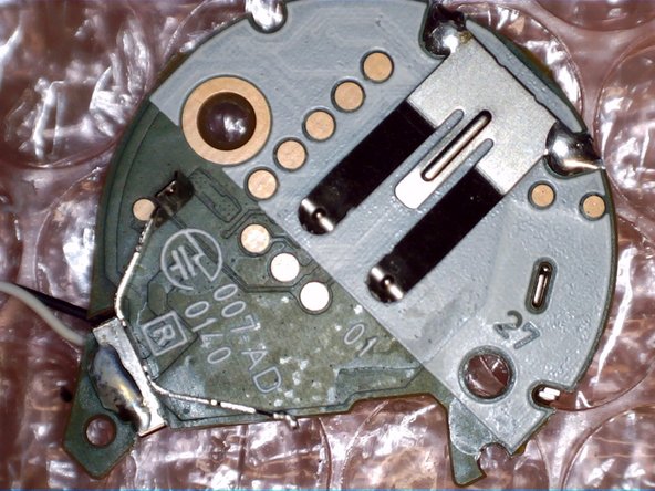
il circuito stampato è posizionato su tre supporti in plastica e tenuto in sede solo dalla pressione delle viti posteriori
-
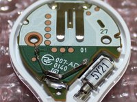
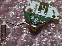
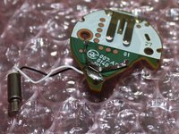
il circuito stampato e il motore di vibrazione possono essere estratti esercitando solo una leggerissima pressione
-
-
-
-
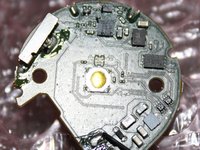
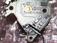
Pulsante funzione situato al centro
-
LED multicolore accanto al pulsante
-
-









18Commenti sulla guida
This post needs moar wisdom
Anybody able to spot a Pedometer?
There is no pedometer. It's just a Bluetooth clicker. Your phone's sensors track all movement.
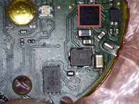
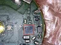
What is the
"A1
HNG
SBJ"
chip in "step 6"?
I2C/SPI flash?
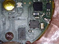
And.. what is in "Step 4" the chip? in between the capacitors and that "mostlikely MOSFETs for driving LEDs".
I'm looking at DA14580 modules on ebay:
http://www.ebay.com/sch/i.html?_from=R40...
And I tend to to say "let's try to clone this", the DA14580 has OTA programmable FLASH. :)
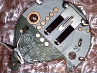
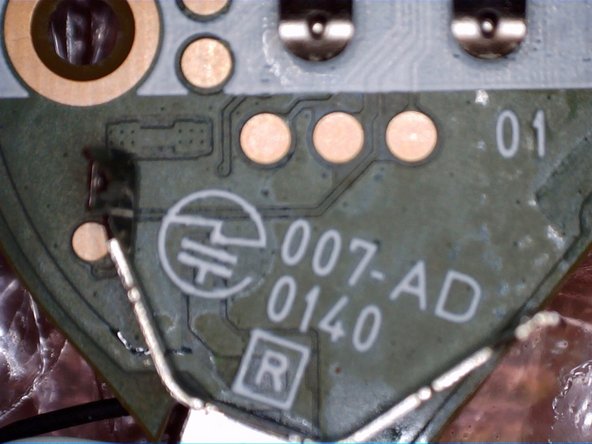
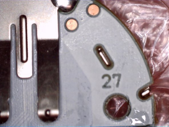
Last picture is most likely JTAG pogo contact points. For programming and testing. The board seems to be like 3-4+ layer board just based on the pictures. Also can't really tell you what chips those are with that quality of a picture. However the two little chips under the mounting hole on the picture in step 4 looks to be the DC Boost IC to keep constant voltage throughout the batteries life. The chip to the left of those boost converts is most likely the Bluetooth IC (just guessing by the location and the traces around it). Hope this helps :)
