Salta al contenuto principale

Questa versione può contenere modifiche errate. Passa all'ultima istantanea verificata.

Cosa ti serve

  1. Questo passaggio è privo di traduzione. Aiuta a tradurlo

    : passo 1, immagine 1 di 3 : passo 1, immagine 2 di 3 : passo 1, immagine 3 di 3
    Attrezzo utilizzato in questo passaggio:
    iOpener
    $19.99
    Compra
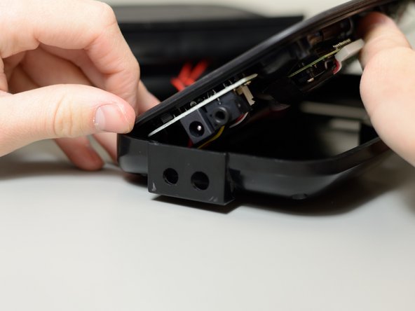
    • Pry the exterior housing off the iHome iP37. You may need extra leverage to do this.

    • Note: This step is the most difficult due to the way it is attached. The glue holding the exterior housing to the internals does not break easily. You may want to use iFixit's iOpener to soften the glue.

    • Note: The process is the same for both the upper half and the lower half. To identify the halves, look for these details: the upper half has a metal grid, and the lower half has buttons. If you are replacing any other components, pry off the lower half.

  2. Questo passaggio è privo di traduzione. Aiuta a tradurlo

    : passo 2, immagine 1 di 3 : passo 2, immagine 2 di 3 : passo 2, immagine 3 di 3
    • Remove these four 9 mm screws from the plastic casing; you will need a Phillips #2 driver to do this.

    • Remove the flanged 9 mm screw from the counterweight; you will need a Phillips #2 driver to do this.

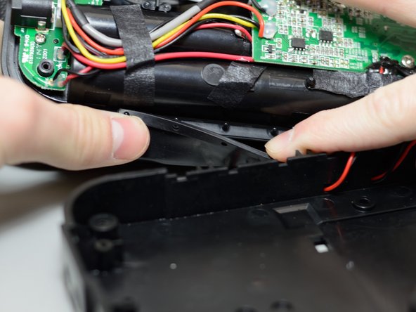
    • Lift and remove the counterweight.

  3. Questo passaggio è privo di traduzione. Aiuta a tradurlo

    : passo 3, immagine 1 di 3 : passo 3, immagine 2 di 3 : passo 3, immagine 3 di 3
    • Lift and remove the plastic casing.

    • Note: It is best to lift the casing starting from the side without the protruding 3.5mm audio port and power port.

    • Reminder: During this process, a rubber cover will likely be dislodged. Make sure to re-seat this cover on the small pegs before putting the plastic casing back on.

  4. Questo passaggio è privo di traduzione. Aiuta a tradurlo

    : passo 4, immagine 1 di 1
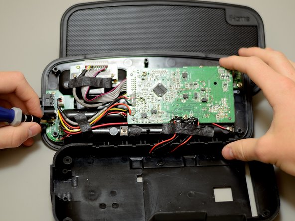
    • Firmly and cautiously unplug the two white 3-pin connectors from the printed circuit board.

  5. Questo passaggio è privo di traduzione. Aiuta a tradurlo

    : passo 5, immagine 1 di 3 : passo 5, immagine 2 di 3 : passo 5, immagine 3 di 3
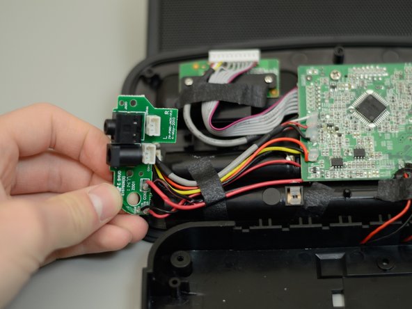
    • Remove the two 5mm screws holding the power and 3.5mm jack PCB onto the rest of the device; you will need a Phillips #1 driver to do this.

    • Lift the PCB away from the rest of the device.

  6. Questo passaggio è privo di traduzione. Aiuta a tradurlo

    : passo 6, immagine 1 di 1
    • Desolder the two black and two red cables from the board.

    • These wires will need to be soldered to the replacement board when reassembling the device.

    • You can refer to iFixit's guide or this informative video for more information on soldering.

Linea Traguardo

Jerrell

Membro da: 04/23/14

730 Reputazione

7 Guide realizzate

Team

Cal Poly, Team 11-50, Amido Spring 2014 Membro di Cal Poly, Team 11-50, Amido Spring 2014

CPSU-AMIDO-S14S11G50

4 Membri

8 Guide realizzate

0 Commenti

Aggiungi Commento

Visualizza Statistiche:

Ultime 24 Ore: 2

Ultimi 7 Giorni: 10

Ultimi 30 Giorni: 14

Tutti i Tempi: 2,814