Introduzione
Prerequisite Only
This guide will show you how to remove the back panel of the camera so that you can access the inside.
Before you begin, make sure that the battery and SD card have been removed from the camera.
Cosa ti serve
-
-
Using your screwdriver, unscrew the two 5.0 mm Philips screws to the right of the LCD screen.
 Chiedi a FixBot
-
-
-
Flip the camera over to the left side of the screen and unscrew the 5mm Phillips screw found there.
-
-
-
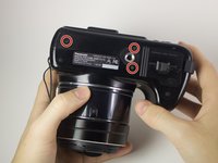
Turn the camera upside down and unscrew the three 5mm screws found on the bottom.
-
-
-
-
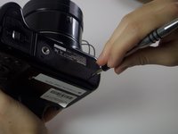
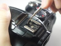
On the top of the camera locate the two rails with a thin sheet of metal on the floor between them.
-
With a metal spudger, lift this sheet and push it out of the rail device to detach it from the camera.
-
-
-
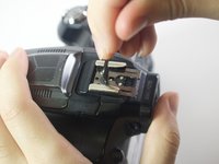
Proceed to remove the four 5mm Phillips screws that you just uncovered.
-
-
-
Slowly pull on both side of the camera, until both halves begin to separate from each other.
-
-
-
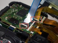
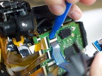
Using a plastic opening tool, carefully flip up the small black levers that attach the ribbon cables to the ZIF connectors on the motherboard.
-
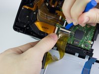
Carefully pull the ribbon cables out of the slot once they have been released.
-


To reassemble your device, follow these instructions in reverse order.

Team

Cal Poly, Team 21-3, Maness Winter 2017 Membro di Cal Poly, Team 21-3, Maness Winter 2017
CPSU-MANESS-W17S21G3
6 Membri
12 guide realizzate