Salta al contenuto principale

Questa versione può contenere modifiche errate. Passa all'ultima istantanea verificata.

Cosa ti serve

  1. , Cover posteriore: passo 1, immagine 1 di 3 , Cover posteriore: passo 1, immagine 2 di 3 , Cover posteriore: passo 1, immagine 3 di 3
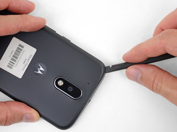
    • Inserisci un'unghia o uno spudger nella cavità del bordo inferiore del telefono, vicino alla porta di ricarica.

    • Torci delicatamente o fai leva per aprire una piccola fessura tra la cover posteriore e il corpo del telefono.

    • Mentre lasci il tuo attrezzo (o la tua unghia) inserito nella fessura tra la cover posteriore e il corpo del telefono, fallo scorrere attorno all'angolo per iniziare a sganciare le clip di plastica che tengono in posizione la cover.

  2. : passo 2, immagine 1 di 2 : passo 2, immagine 2 di 2
    • Fai scorrere il tuo attrezzo lungo il lato del telefono per separare altre clip di fissaggio della cover.

  3. : passo 3, immagine 1 di 3 : passo 3, immagine 2 di 3 : passo 3, immagine 3 di 3
    • Mantieni il tuo attrezzo inserito appena sotto la cover posteriore e fallo scorrere attorno all'angolo superiore.

    • Se necessario, continua a far leva attorno ai lati rimasti del telefono finché la cover posteriore non si stacca.

  4. : passo 4, immagine 1 di 2 : passo 4, immagine 2 di 2
    • Rimuovi la cover posteriore.

    • Per installare la cover posteriore, posizionala con cura sopra il telefono e poi premila delicatamente attorno a tutti i bordi finché non senti che tutte le clip sono scattate in posizione di bloccaggio.

  5. , Telaio centrale: passo 5, immagine 1 di 3 , Telaio centrale: passo 5, immagine 2 di 3 , Telaio centrale: passo 5, immagine 3 di 3
    • Fai scorrere fuori i vassoi delle schede microSD e SIM (se non l'avevi già fatto).

  6. : passo 6, immagine 1 di 2 : passo 6, immagine 2 di 2
    • Usa uno spudger per sollevare la cover di gomma del connettore del flash della fotocamera.

  7. : passo 7, immagine 1 di 1
    • Togli la cover di gomma.

  8. : passo 8, immagine 1 di 2 : passo 8, immagine 2 di 2
    • Usa uno spudger per scollegare, facendo leva da sotto, il connettore del flash della fotocamera.

  9. : passo 9, immagine 1 di 1
    • Usa un cacciavite Torx T3 per rimuovere le 19 viti tutte uguali che fissano il telaio centrale.

  10. : passo 10, immagine 1 di 1
    • Inserisci uno spudger sotto il telaio centrale nel suo angolo superiore sinistro e torci con delicatezza l'attrezzo per separare questa parte dalla scocca del telefono.

  11. : passo 11, immagine 1 di 1
    • Rimuovi il telaio centrale.

  12. Questo passaggio è privo di traduzione. Aiuta a tradurlo

    : passo 12, immagine 1 di 2 : passo 12, immagine 2 di 2
    • Insert a thin tool (such as one of your tweezer tips) under the red and black battery wires, and slide it underneath the battery connector.

    • Gently pry straight up to disconnect the battery.

    • Pry only from the side where the wires attach to the connector—if you pry anywhere else, you may break the socket.

    • During reassembly, align the connector in its socket and then press straight down to reconnect it, wiggling slightly as you press to help it seat correctly.

  13. Questo passaggio è privo di traduzione. Aiuta a tradurlo

    : passo 13, immagine 1 di 2 : passo 13, immagine 2 di 2
    • Peel off any tape securing the battery wires, and then push the battery wires towards the battery to de-route them from the black bracket on the motherboard.

  14. Questo passaggio è privo di traduzione. Aiuta a tradurlo

    : passo 14, immagine 1 di 1
    • It's not necessary to remove the battery in order to remove or replace the motherboard. You can safely ignore the fact that the battery is missing in the remaining images in this guide.

    • Peel up and remove the black rubber cover from the charging port and vibration motor connector.

  15. Questo passaggio è privo di traduzione. Aiuta a tradurlo

    : passo 15, immagine 1 di 2 : passo 15, immagine 2 di 2
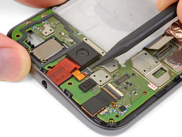
    • Insert the point of your spudger underneath the vibration motor, and gently pry up to separate it from the frame.

  16. Questo passaggio è privo di traduzione. Aiuta a tradurlo

    : passo 16, immagine 1 di 1
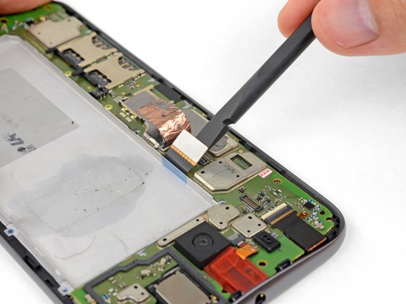
    • Peel up the copper tape covering the display connector.

    • This tape provides protection from electromagnetic interference. Keep it in one piece if possible, and carefully fold it back into position when your repair is complete.

  17. Questo passaggio è privo di traduzione. Aiuta a tradurlo

    : passo 17, immagine 1 di 2 : passo 17, immagine 2 di 2
    • Use your spudger to disconnect the display by prying its connector straight up from the motherboard, on the edge nearest the side of the phone.

  18. Questo passaggio è privo di traduzione. Aiuta a tradurlo

    : passo 18, immagine 1 di 2 : passo 18, immagine 2 di 2
    • Pry up with your spudger to flip open the locking flap on the headphone jack's ZIF connector.

    • It's possible to disconnect the headphone jack at this point by pulling its orange flex cable straight out of the ZIF socket, but it's easy to tear the cable if you're not careful. For a better method, continue with the steps below.

  19. Questo passaggio è privo di traduzione. Aiuta a tradurlo

    : passo 19, immagine 1 di 1
    • Use a T3 Torx driver to remove the two bronze-colored, 2.4 mm screws securing the motherboard.

  20. Questo passaggio è privo di traduzione. Aiuta a tradurlo

    : passo 20, immagine 1 di 3 : passo 20, immagine 2 di 3 : passo 20, immagine 3 di 3
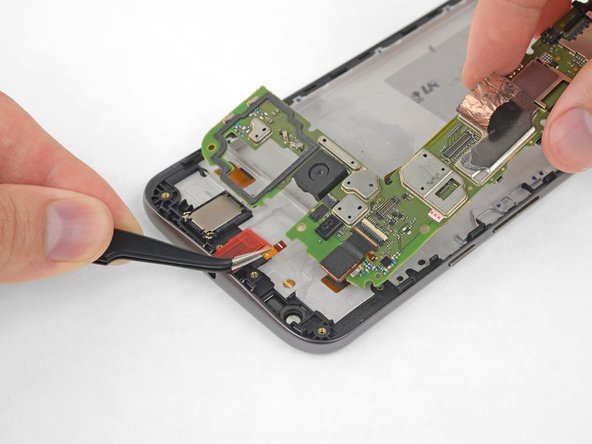
    • Grasping the motherboard by its edges, left the bottom end up at an angle, while keeping the top edge close to the phone.

    • Use your spudger to pry up the front-facing camera and make sure it separates safely from the frame. The camera can remain attached to the motherboard.

    • Using your tweezers, grasp the headphone jack flex cable and carefully pull it out of its socket as you remove the motherboard.

    • Remove the motherboard.

    • If you feel any resistance, stop. Make sure there are no components still holding the frame to the motherboard.

  21. Questo passaggio è privo di traduzione. Aiuta a tradurlo

    • If desired, remove the remaining components from the motherboard (cameras and vibration motor).

Linea Traguardo

Altre 8 persone hanno completato questa guida.

Kierra Schau

Membro da: 09/28/17

1.511 Reputazione

4 Guide realizzate

Team

USF Tampa, Team S11-G2, Passmore Fall 2017 Membro di USF Tampa, Team S11-G2, Passmore Fall 2017

USFT-PASSMORE-F17S11G2

3 Membri

13 Guide realizzate

0 Commenti

Aggiungi Commento

Visualizza Statistiche:

Ultime 24 Ore: 0

Ultimi 7 Giorni: 5

Ultimi 30 Giorni: 21

Tutti i Tempi: 8,645