Salta al contenuto principale

Questa guida ha delle modifiche più recenti. Passa all'ultima versione non verificata.

Logitech Harmony Smart Control Charging Port Replacement

Cosa ti serve

  1. Logitech Harmony Smart Control Charging Port Replacement, Charging Port: passo 1, immagine 1 di 2 Logitech Harmony Smart Control Charging Port Replacement, Charging Port: passo 1, immagine 2 di 2
    • Use the plastic opening tool to lift up the rubber pad.

    • With your fingers, pull back the rubber pad. This will expose the screw holes on the bottom of the device.

    • Repeat the step above for the second rubber pad on the bottom of the hub.

  2. Logitech Harmony Smart Control Charging Port Replacement: passo 2, immagine 1 di 2 Logitech Harmony Smart Control Charging Port Replacement: passo 2, immagine 2 di 2
    • Using the PH00 bit, remove the four 6mm Phillips screws

  3. Logitech Harmony Smart Control Charging Port Replacement: passo 3, immagine 1 di 2 Logitech Harmony Smart Control Charging Port Replacement: passo 3, immagine 2 di 2
    • Use the plastic opening tool to pry open and separate the pieces of plastic from each other.

  4. Logitech Harmony Smart Control Charging Port Replacement: passo 4, immagine 1 di 2 Logitech Harmony Smart Control Charging Port Replacement: passo 4, immagine 2 di 2
    • Using the PH00 bit, remove the three 4mm Phillips screws.

  5. Logitech Harmony Smart Control Charging Port Replacement: passo 5, immagine 1 di 3 Logitech Harmony Smart Control Charging Port Replacement: passo 5, immagine 2 di 3 Logitech Harmony Smart Control Charging Port Replacement: passo 5, immagine 3 di 3
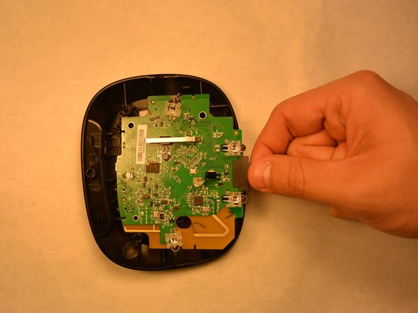
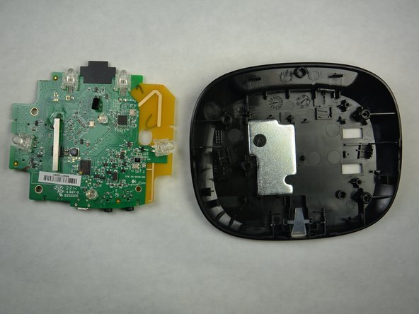
    • Starting at the yellow corner, use a plastic opening tool to pry the circuit board from the housing.

  6. Logitech Harmony Smart Control Charging Port Replacement: passo 6, immagine 1 di 3 Logitech Harmony Smart Control Charging Port Replacement: passo 6, immagine 2 di 3 Logitech Harmony Smart Control Charging Port Replacement: passo 6, immagine 3 di 3
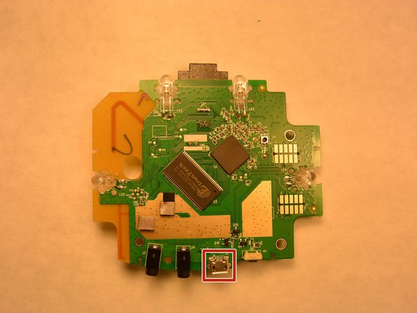
    • Locate the defective charging port.

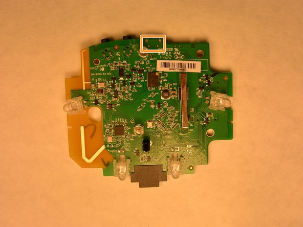
    • Turn the circuit board over to expose the charging solder.

    • Using a soldering iron, remove the solder and the charging port. Install a new charging port and solder.

Conclusione

To reassemble your device, follow these instructions in reverse order.

Un'altra persona ha completato questa guida.

Team

IUPUI, Team 3-2, Harley Fall 2015 Membro di IUPUI, Team 3-2, Harley Fall 2015

IUPUI-HARLEY-F15S3G2

4 Membri

5 Guide realizzate

0 Commenti

Aggiungi Commento

Visualizza Statistiche:

Ultime 24 Ore: 0

Ultimi 7 Giorni: 6

Ultimi 30 Giorni: 13

Tutti i Tempi: 716