Introduzione
Use this guide to fix a faulty logic board in your iPhone 6s. Repairing a logic board may require micro-soldering.
A faulty logic board can also be replaced using the steps in this guide. It's important to note that each iPhone's logic board and Touch ID fingerprint sensor are paired at the factory, so replacing the logic board will disable Touch ID unless you also install a replacement home button that has been properly paired to your new logic board.
You can also use this guide for reference to replace the logic board EMI shield stickers.
See this iPhone 6s iTunes Hardware Restoration guide to help fix your phone’s logic board.
Cosa ti serve
Panoramica Video
Fix iPhone 6s iTunes Error
-
-
Remove the two 3.4 mm P2 Pentalobe screws on the bottom edge of the iPhone, on either side of the Lightning connector.
-
-
Attrezzo utilizzato in questo passaggio:Clampy - Anti-Clamp$24.95
-
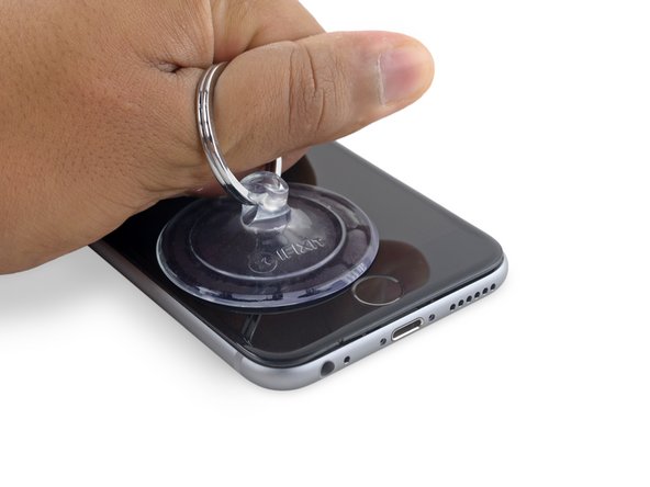
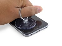
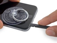
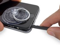
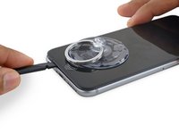
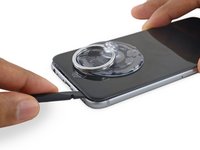
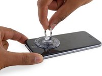
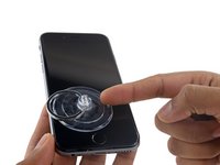
If you don't have an Anti-Clamp, follow the next three steps to use a suction handle.
-
Apply mild heat to the lower edge of the iPhone using an iOpener or hair dryer for about a minute.
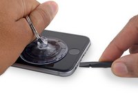
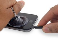
-
-
-
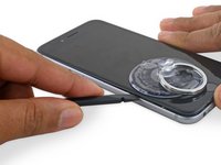
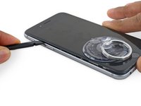
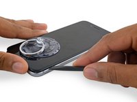
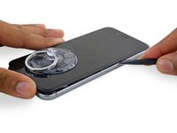
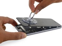
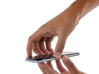
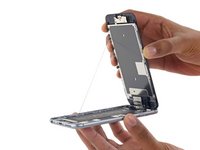
Gently grasp the display assembly and lift it up to open the phone, using the clips at the top of the front panel as a hinge.
-
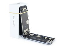
Open the display to about a 90º angle, and lean it against something to keep it propped up while you're working on the phone.
-
Add a rubber band to keep the display securely in place while you work. This prevents undue strain on the display cables.
-
-
Attrezzo utilizzato in questo passaggio:Magnetic Project Mat$19.95
-
Remove two Phillips screws securing the battery connector bracket, of the following lengths:
-
One 2.9 mm screw
-
One 2.2 mm screw
-
-
-
-
Remove the following four Phillips screws securing the display cable bracket:
-
Three 1.2 mm screws
-
One 2.8 mm screw
-
-
-
Use the flat end of a spudger to disconnect the rear camera from its socket on the logic board.
-
-
-
Insert a SIM card eject tool or a paperclip into the small hole in the SIM card tray.
-
Press to eject the tray.
-
-
-
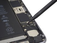
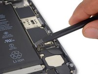
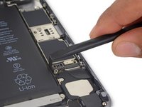
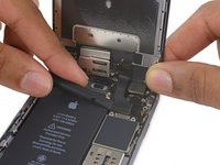
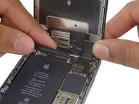
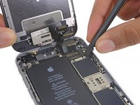
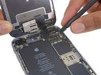
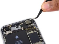
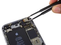
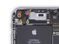
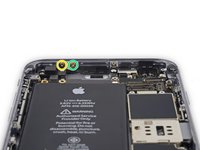
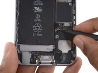
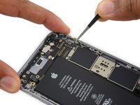
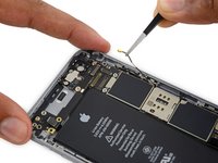
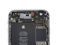
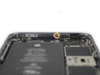
Remove the two 2.3 mm Phillips screws securing the upper component cable connector bracket.
-
-
-
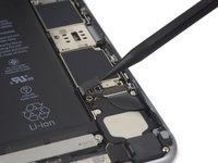
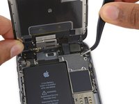
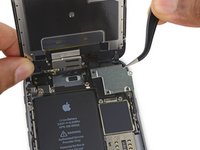
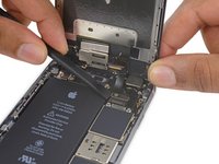
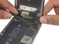
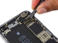
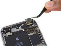
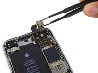
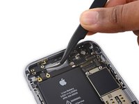
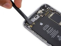
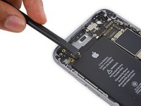
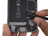
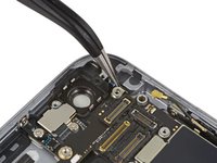
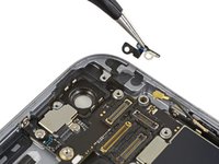
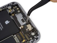
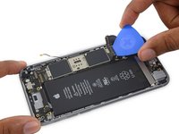
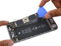
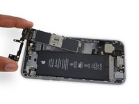
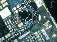
Remove the protective cover from the logic board.
-
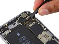
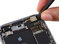
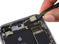
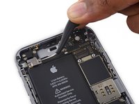
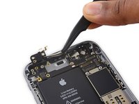
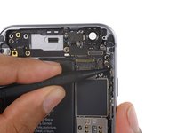
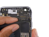
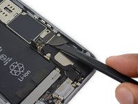
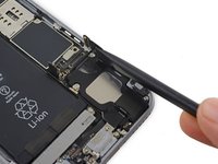
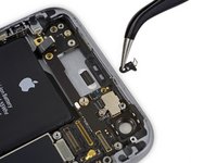
Remove the black sticker from the logic board.
-


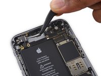


To reassemble your device, follow these instructions in reverse order.
To reassemble your device, follow these instructions in reverse order.
Annulla: non ho completato questa guida.
Altre 10 persone hanno completato questa guida.