Introduzione
When the function keys fail to register, it may be because the function key motherboard has been damaged. This guide will show you how to replace the motherboard in question.
Cosa ti serve
-
-
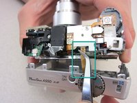
Unscrew a total of 6 4.45 mm phillips head screws using a #00 phillips head screwdriver.
-
There are 2 screws on the left side (when looking at the front of the camera).
-
There are 3 screws on the bottom
-
There is 1 screw on the right side
 Chiedi a FixBot
-
-
-
Turn to the bottom of the camera.
-
Open the memory card cover by sliding the "CARD/BATT." button up, and then pulling the cover to the left.
-
-
-
This is what the SD card/battery compartment looks like when opened.
-
Remove one 4.45mm phillips head screw from the SD card/battery compartment using a #00 phillips head screwdriver.
-
-
-
Strumento utilizzato in questo passaggio:Tweezers$4.99
-
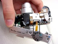
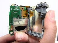
Start from the battery compartment and remove the back cover.
-
Remove the connecting ribbon from the body of the camera using a pair of tweezers.
-
-
-
Once the ribbon connecting the back cover is removed, the back of the camera body should look like this.
-
-
-
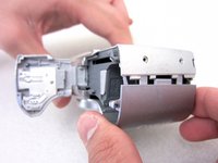
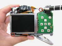
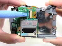
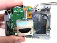
Remove 2 4.35mm phillips head screws from around the LCD screen using a #00 phillips head screwdriver.
-
Loosen the black ribbon clamp using an iPod opening tool
-
Release the LCD screen by removing the ribbon from the body of the camera.
-
-
-
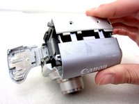
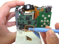
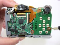
Unscrew 2 3.35mm phillips head screw from the face of the function key motherboard using a #00 phillips head screwdriver.
-
-
Strumento utilizzato in questo passaggio:Tweezers$4.99
-
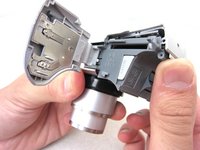
Release the black ribbon clamp attached to the back of the motherboard using an iPod opening tool to lift the clamp.
-
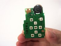
Remove the ribbon connecting the function key motherboard from the body of the camera using tweezers.
-
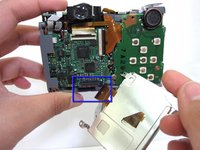
The function key motherboard has the SD card reader attached to the back. The motherboard and SD card combination should be replaced.
-


To reassemble your device, follow these instructions in reverse order.
Annulla: non ho completato questa guida.
Un'altra persona ha completato questa guida.
Team

Cal Poly, Team 8-6, Regan Spring 2011 Membro di Cal Poly, Team 8-6, Regan Spring 2011
CPSU-REGAN-S11S8G6
4 Membri
22 guide realizzate