Introduzione
Use this guide to replace the display assembly, including the LCD screen, front glass and digitizer, on your Fairphone.
Cosa ti serve
-
-
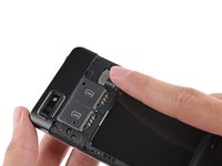
With the indentation as leverage, use your fingernail to pry the bottom portion of the back cover from the phone.
 Chiedi a FixBot
-
-
-
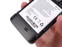
Use a fingernail in this indentation to push the battery toward the top of the phone
-
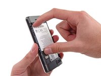
Pull the battery out away from the phone.
-
-
-
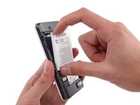
Use your finger to slide the SIM card straight down out of its tray.
-
Remove the SIM card from your Fairphone.
-
-
-
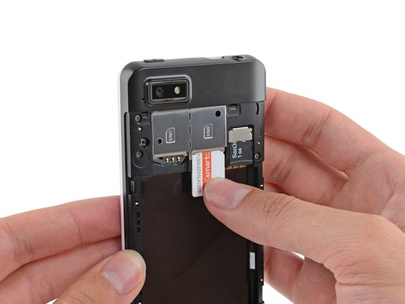
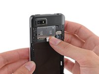
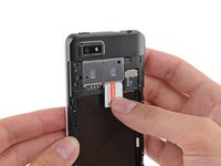
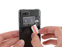
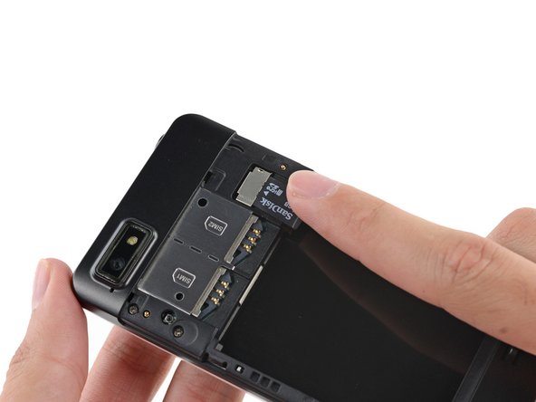
If you have a microSD card, use your finger to slide it straight out of its slot.
-
Remove the microSD card from your phone.
-
-
-
Remove the five 3.9 mm Phillips #000 screws securing the midframe to the display assembly.
-
-
-
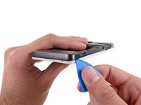
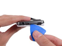
Use an opening pick to carefully pry the midframe away from the display assembly.
-
Start just below the volume rocker and work your way down toward the bottom of the phone, freeing the plastic clips along the side.
-
-
-
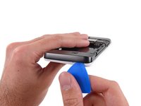
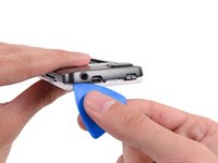
Carefully round the corner, separating the midframe from the display assembly.
-
-
-
-
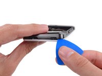
Separate any remaining clips and remove the midframe from the phone.
-
-
Strumento utilizzato in questo passaggio:Tweezers$4.99
-
Use tweezers to remove the volume rocker and power buttons from the display assembly.
-
-
-
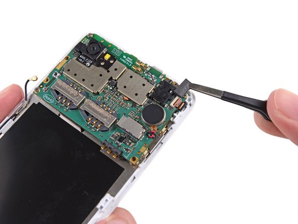
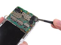
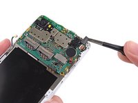
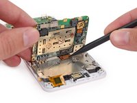
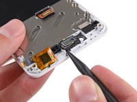
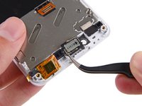
Use the flat end of a spudger to disconnect the antenna cable connector.
-
-
-
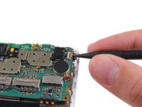
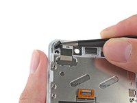
Use tweezers to remove the adhesive foam tape from the top of the digitizer cable ZIF socket.
-
-
-
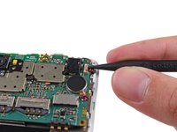
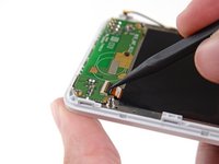
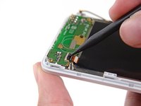
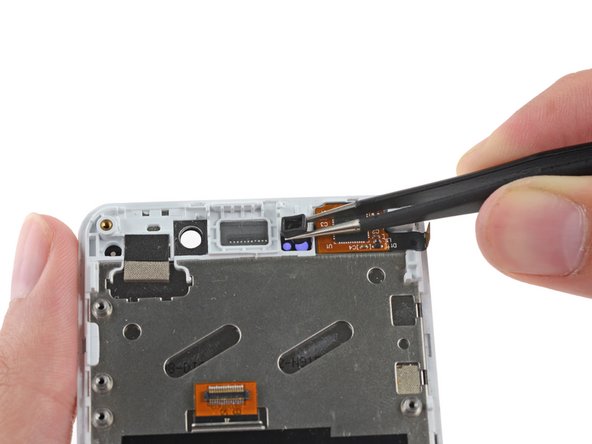
Use the tip of a spudger to flip open the tab on the digitizer ZIF connector.
-
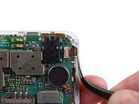
Use tweezers to pull the digitizer cable away from its socket on the motherboard.
-
-
-
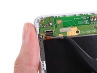
Remove the three 2.5 mm Phillips #000 screws securing the motherboard to the display assembly.
-
-
-
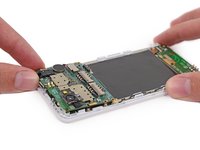
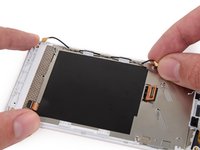
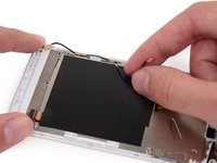
Gently lift the top end of the motherboard up to expose the display data cable.
-
-
-
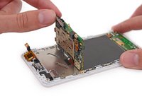
Use the tip of a spudger to disconnect the display data cable from the back of the motherboard.
-
-
-
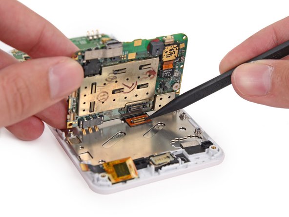
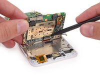
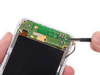
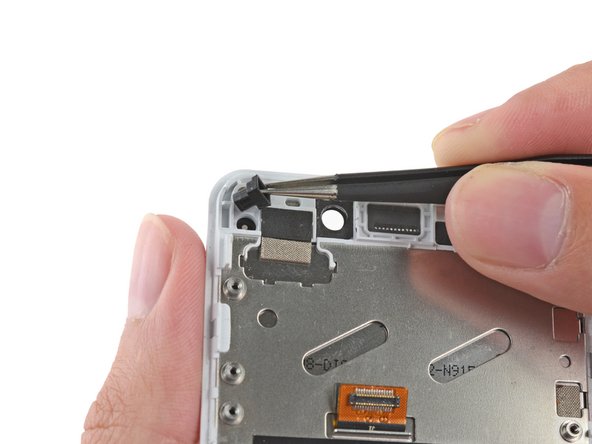
Use the flat end of a spudger to disconnect the antenna cable connector.
-
-
Strumento utilizzato in questo passaggio:Tweezers$4.99
-
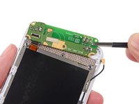
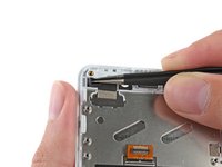
Use the tip of a spudger to flip open the tab on the daughterboard data cable ZIF connector.
-
Use tweezers to pull the daughterboard data cable away from its socket.
-
-
-
Remove the following screws securing the Wi-Fi daughterboard to the display assembly:
-
Two 2.5 mm Phillips #000 screws
-
One 1.6 mm Phillips #000 screw
-
-
-
Use tweezers to gently pry the board up and remove it from the phone.
-
-
-
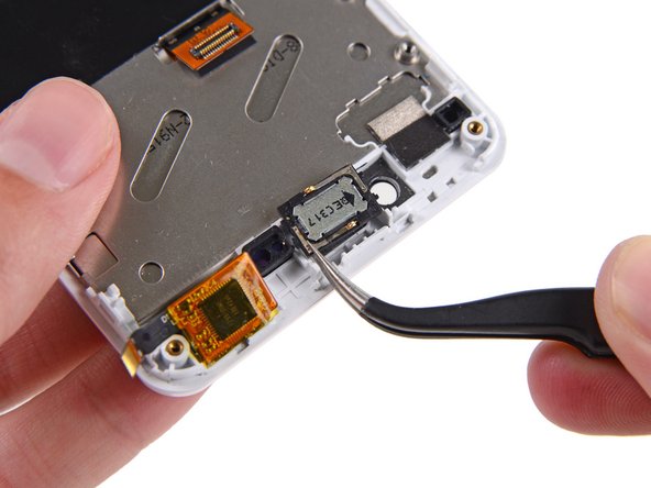
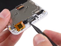
Use the tip of a spudger to gently pry the speaker up from the display assembly.
-
Remove the speaker.
-
-
-
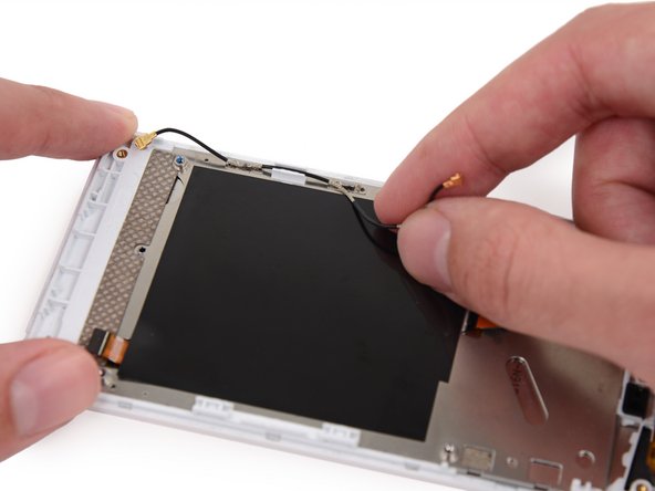
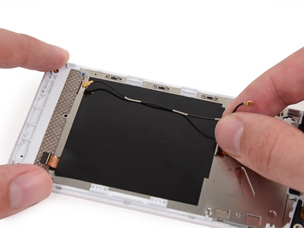
Remove the antenna interconnect cable from the display assembly.
-
-
-
Remove the rubber guide from the recess near the front facing camera hole.
-
-
-
Remove the rubber guide to the right of the earpiece speaker recess.
-
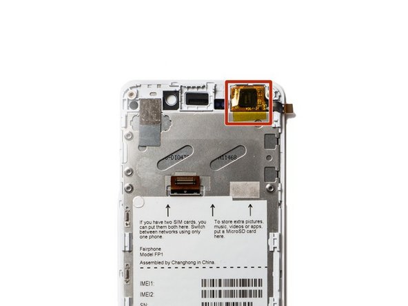
Your replacement display will have a piece of yellow tape covering the touch sensor chip. Do not remove this tape; if you do, your phone may not work after reassembly.
-


To reassemble your device, follow these instructions in reverse order.
Annulla: non ho completato questa guida.
Altre 102 persone hanno completato questa guida.


16Commenti sulla guida
The Camera is not mentioned at all. It's glued to the Display and yet still working, it can't focus anymore. So I might have to get a new one as well.
Awesome! Did it, and everything still works. Mighty pleased with myself. Thank you, iFixit!!!