Questa versione può contenere modifiche errate. Passa all'ultima istantanea verificata.
Cosa ti serve
-
Questo passaggio è privo di traduzione. Aiuta a tradurlo
-
Begin by placing the camera upside down and removing the three small center screws.
-
-
Questo passaggio è privo di traduzione. Aiuta a tradurlo
-
Turn the camera on its side (Counterclockwise). Remove the two small screws on either side of the silver panel.
-
Turn the camera 180 degrees onto its other side and remove the two small screws on either side of the silver panel.
-
-
Questo passaggio è privo di traduzione. Aiuta a tradurlo
-
Locate the camera's tripod mount located on the bottom of the camera.
-
Carefully remove the camera's tripod mount and place it aside.
-
Be careful not to lose this piece.
-
Rotate the silver panel labeled 4x clockwise.
-
-
Questo passaggio è privo di traduzione. Aiuta a tradurlo
-
Align the camera so that the side with "4x Optical Zoom" is facing toward you.
-
Gently twist the bottom corner clockwise until you feel the side panel unlock.
-
Lift off the side panel and set aside.
-
-
Questo passaggio è privo di traduzione. Aiuta a tradurlo
-
Rotate the camera 180 degrees to face the side panel with the lanyard loop on it.
-
Gently lift the panel vertically until it lifts off
-
-
-
Questo passaggio è privo di traduzione. Aiuta a tradurlo
-
Position the camera so the bottom is facing up and the display away from the surface.
-
Gently pry the screen portion from the camera portion with your fingers or a plastic prybar.
-
Lay the display flat to expose the circuit board and the display control ribbon cables.
-
-
Questo passaggio è privo di traduzione. Aiuta a tradurlo
-
Using a flat head screw driver gently pry up the tab securing the ribbon cable from the display screen to the camera sensor and battery housing.
-
Remove the ribbon cable connecting LCD display to camera sensor and battery housing
-
Following the same procedure as above, uninstall the ribbon cable connecting the main camera controls to the camera sensor and battery housing
-
-
Questo passaggio è privo di traduzione. Aiuta a tradurlo
-
The LCD display screen is now removed from the camera sensor and battery housing.
-
The main camera controls are now removed from the camera sensor and battery housing.
-
-
Questo passaggio è privo di traduzione. Aiuta a tradurlo
-
Unsnap LCD display screen from its mount by unsnapping it from the display screen using your finger nail.
-
Now the new LCD screen can be installed.
-
-
Questo passaggio è privo di traduzione. Aiuta a tradurlo
-
Using a flat head screw driver gently pry up on the tab securing the larger ribbon cable which connects the display screen and camera sensor / battery housing.
-
Remove the ribbon cable connecting the LCD display and camera sensor / battery housing.
-
Following the same procedure, uninstall the ribbon cable connecting the main camera controls to the camera sensor and battery housing
-
-
Questo passaggio è privo di traduzione. Aiuta a tradurlo
-
Now turn your attention to the camera sensor and battery housing. Identify the two connection points of the large ribbon cable.
-
Carefully place a flathead screwdriver under the left ribbon cable connection point and pull up to disconnect.
-
Repeat the previous step but this time carefully remove the right ribbon cable connection point.
-
After both sides of the ribbon cable have been disconnected it is ready to be replaced.
-
-
Questo passaggio è privo di traduzione. Aiuta a tradurlo
-
After removal of the LCD screen and ribbon cable the camera sensor can be accessed.
-
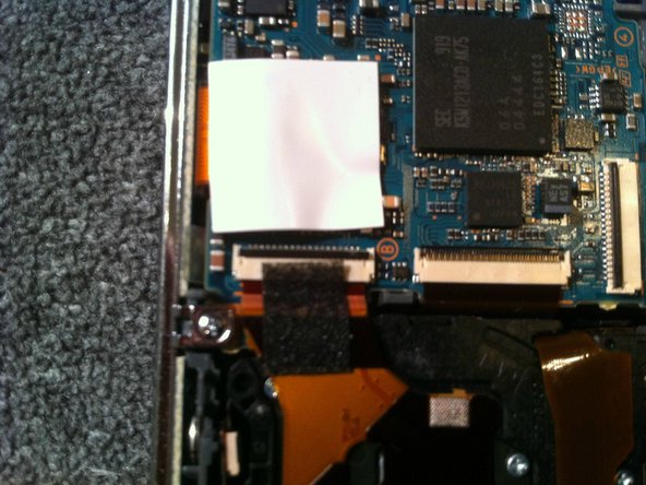
Position the camera with the circuit board facing up, showing the two ribbon cables connecting the camera sensor.
-
Gently pry the black tabs on both cables until they are flipped up.
-
Gently pull the ribbon cables until they slide out of the connectors.
-
-
Questo passaggio è privo di traduzione. Aiuta a tradurlo
-
Flip the camera over so the shutter is facing up and the top buttons are away from you.
-
Making sure the ribbon cables are free, lift the battery housing up while keeping the camera sensor on the table, this will flip it up and provide access to the shutter button cable.
-
Gently slide out the cable to free the camera sensor from the rest of the housing.
-


Team

Clemson, Team 2-3, Benson Spring 2012 Membro di Clemson, Team 2-3, Benson Spring 2012
CLEM-BENSON-S12S2G3
3 Membri
11 Guide realizzate