Questa versione può contenere modifiche errate. Passa all'ultima istantanea verificata.
Cosa ti serve
-
Questo passaggio è privo di traduzione. Aiuta a tradurlo
-
Remove two 6.8 mm JIS #000 screws on the right side.
-
Remove six 5.3 mm JIS #000 screws on the bottom.
-
Remove two 5.3 mm JIS #000 screws on either side of the viewfinder.
-
-
Questo passaggio è privo di traduzione. Aiuta a tradurlo
-
Remove one 5.9 mm JIS #000 screw on the top right.
-
Remove one 3.4 mm JIS #000 screw on the top left.
-
-
Questo passaggio è privo di traduzione. Aiuta a tradurlo
-
Using a metal spudger, pry the rubber grip off of the casing on the left side of the camera.
-
Remove five silver 5.8 mm JIS #000 screws from underneath the grip.
-
-
Questo passaggio è privo di traduzione. Aiuta a tradurlo
-
Using the metal spudger, pry the rubber grip located just below the turndial.
-
-
Questo passaggio è privo di traduzione. Aiuta a tradurlo
-
Carefully use the plastic opening tool to pry the casing apart along the seam.
-
Follow the seam with the plastic tool until the back is ready to remove.
-
-
Questo passaggio è privo di traduzione. Aiuta a tradurlo
-
To disconnect the white wire, pinch the wire casing and pull it directly out from the camera.
-
To disconnect the ribbon connector, softly pull the back away from the motherboard. It should come undone with little force.
-
Once removed, set the back in a safe place.
-
-
-
Questo passaggio è privo di traduzione. Aiuta a tradurlo
-
Remove the five ribbon connectors along the bottom of the assembly using either needle nose tweezers or a plastic opening tool to flip the small flaps to the "up" position.
-
Use a nylon spudger to pull each ribbon connector out of its connection using the hole in the center of the ribbon.
-
-
Questo passaggio è privo di traduzione. Aiuta a tradurlo
-
Remove the button cell battery from the motherboard using a pair of tweezers.
-
-
Questo passaggio è privo di traduzione. Aiuta a tradurlo
-
Disconnect the small plastic connectors on the top left corner of the motherboard by gripping the small plastic portion of the wire and gently pulling out of the connector.
-
Disconnect the three ribbon connectors along the top.
-
-
Questo passaggio è privo di traduzione. Aiuta a tradurlo
-
Remove the four screws from the front of the camera. There are two screws above the lens mount and two screws inside the lens mount.
-
Remove the four screws from the bottom of the camera.
-
-
Questo passaggio è privo di traduzione. Aiuta a tradurlo
-
Using the plastic opening tool, pry the front of the casing off of the camera.
-
-
Questo passaggio è privo di traduzione. Aiuta a tradurlo
-
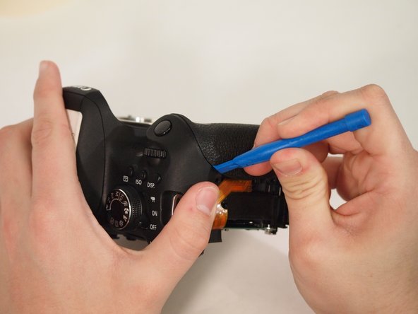
Remove the yellow and red connections on the front near the black cylinder (capacitor).
-
The yellow connector will just pop out if pried from the bottom using a plastic opening tool.
-
The red connector will pull out of the casing with either a plastic opening tool or a thin set of tweezers.
-
-
Questo passaggio è privo di traduzione. Aiuta a tradurlo
-
Remove the diopter adjustment knob next to the viewfinder using a JIS #000 screwdriver.
-
-
Questo passaggio è privo di traduzione. Aiuta a tradurlo
-
Remove the entire upper flash assembly by gently pulling it up and off the camera.
-
-
Questo passaggio è privo di traduzione. Aiuta a tradurlo
-
Disconnect the ribbon connector on the upper right side of the motherboard.
-
Pull back the foam on the connector on the far right side of the motherboard.
-
Flip up the tab on the connector and remove the cable.
-
-
Questo passaggio è privo di traduzione. Aiuta a tradurlo
-
Remove the two screws on the right side of the motherboard as well as the screw in the center.
-
-
Questo passaggio è privo di traduzione. Aiuta a tradurlo
-
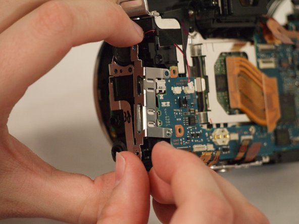
Remove the two screws connecting the metal port bracket to the motherboard.
-
Slide the metal bracket out of the camera.
-


Annulla: non ho completato questa guida.
Altre 7 persone hanno completato questa guida.
Team

University of Memphis, Team S2-G1, Kim Spring 2018 Membro di University of Memphis, Team S2-G1, Kim Spring 2018
UM-KIM-S18S2G1
3 Membri
11 Guide realizzate
2 Commenti
Good tutorial! Two things I noticed on my teardown, on step 6 the white grounding wire has two black tabs on either side you can lift with a guitar pick, much better than pulling on the wire casing; on step 12 the picture is misleading as you pull the plug out towards the middle of the body. Those are very minor things, this was an extremely helpful tutorial! Not for the faint of heart aha