Introduzione
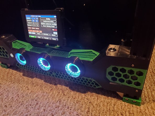
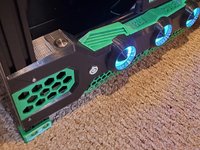
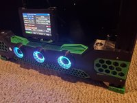
Ben has completely revised the Front Panel design and it looks absolutely amazing. At the time of writing this it's compatible with the FYSETC PanelDue 4.3 clone.
Printed parts needed:
1x Left Panel Face.stl
1x Left Small Panel.stl
1x Right Panel.stl
1x Right Small Panel.stl
1x Left Circle.stl
3x L Inner Fan.stl
3x L tip.stl
1x Right Circle.stl
1x Middle Circle.stl
1x Left Grill.stl
1x Left Lower Grill.stl
1x Right Grill.stl
1x Right Lower Grill.stl
1x Left Net.stl
1x Right Net.stl
1x Middle BLV Name Plate.stl
1x Letters
To make it easier print 3x L tips and 3x L Inner Fan instead of each individual L/M/R Tips and inner fans
Cosa ti serve
-
-
-
Start by placing the NeoPixel rings into the circles. Make sure the pins are at the top center.
-
Thread the Inner Fan part into the circle.
-
Thread the tip into the Inner Fan.
 Chiedi a FixBot
-
-
-
Screw the assembled Circle parts into the Front Face using 12x M3x8 countersunk screws
-
-
-
Glue the letters into the Middle Name Plate
-
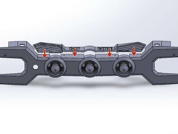
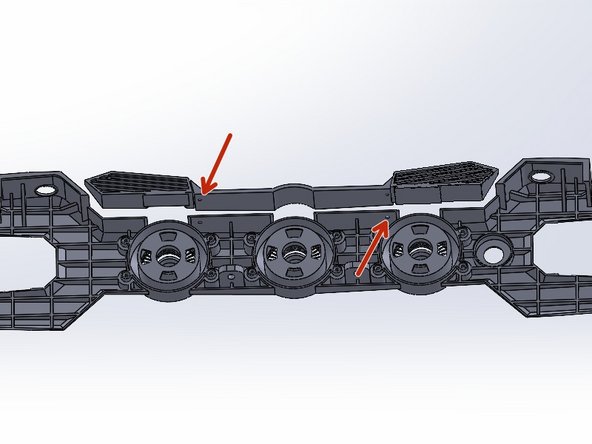
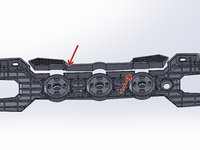
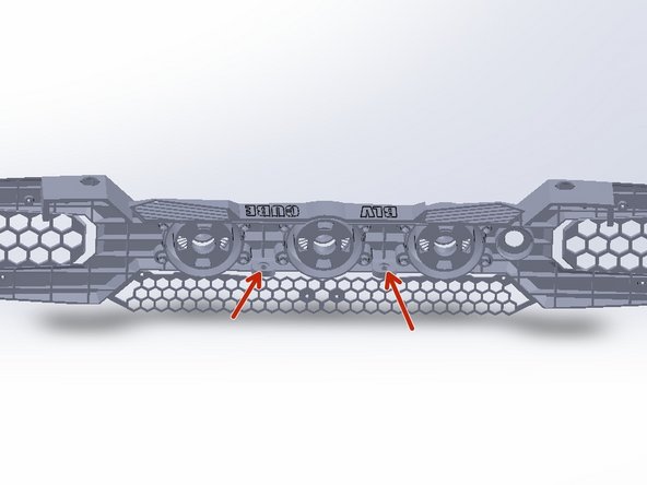
Slide in the Middle Name Plate, Left and Right Nets into the Assembled Front Panel
-
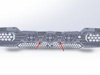
Using 2x M3x8 button head screws secure the Middle Name Plate to the Assembled Front Panel.
-
-
-
-
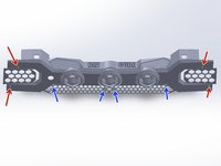
Slide in the Left and Right Grill into the Front Panel Assembly
-
-
-
The Front Panel mounts to the Frame with 4x M3x8 socket head/button head screws with 4x M3 T-Nuts and 2x M5x10 button head screws with 2 M5 T-Nuts
-
The Left and Right Lower Front Grill mount to the frame of the printer with 4x M3x8 button head screws with 4x M3 T-Nuts
-
-
-
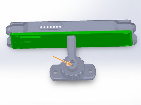
Mount the backplate to the arm with 2x M3x8 button head screws.
-
Mount the ball to the arm with 1x M3x8 socket head screw.
-
I also used a drop of superglue.
-
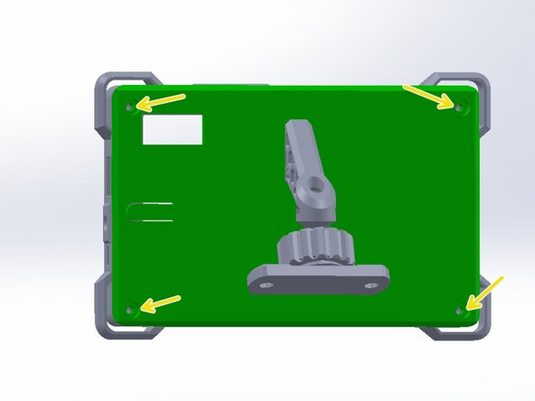
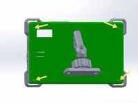
Insert the PanelDue into the backplate lining up the screw holes. Screw the backplate to the front plate with 4x M3x10 button head screws.
-
Mount the full assembly to the front frame re-enforcement with 2x M5x10 button head screws and 2x M5 T-nuts
-
-






Annulla: non ho completato questa guida.
Altre 4 persone hanno completato questa guida.