Non in elenco
Questo wiki non comparirà nei risultati di ricerca, ma può ancora essere visualizzato da chiunque!
Dare to Repair—Phase 2a: Scanning

This is one in a series of guides used in our Dare to Repair 3D-Printed Repair Parts Contest. This guide describes the first phase of the project: Decomposition. First-time readers are advised to read the whole guide; experienced readers can use the quicklist in each step to guide.
For more information—including rules, submission guidelines, and prizes— check out our Dare to Repair contest announcement on our blog. Don't forget, your submissions are due on Monday, May 14.
For easy reference, here's a complete list of guides in this series:
- Phase 1: Decomposition
- Phase 2a: Remodeling with 3D Scanning
- Phase 2b: Remodeling with CAD
- Phase 3: Reproduction
Reviewing Your Part
- Is the part intact? If pieces of the part are missing, consider ‘restoring’ them (with clay, for example), before scanning. Missing geometry is very hard to repair digitally.
- Make sure the part is not shiny, reflective, translucent/transparent, black or white. If so, try to spray it with a matte paint or chalk.
- Are there any critical, sharp edges or corners? 3D scanning results in rounded off shapes. Alterations to the resulting scan model can be done later on.
Step 1: Background Information

In the previous phase, we focused on examining and classifying the shapes in your part. If you found that your part has mostly curved, organic shapes, you probably decided that 3D scanning was the way to go.
Generally speaking, 3D scanning captures an object’s geometry by finding and measuring a large number of points on the surface of it. These points are represented in three-dimensional coordinates called vertices. When these vertices are connected, triangular facets between them make up a mesh surface, which is always an approximation of the original surface. The higher the density of vertices (resolution) in the mesh, the more accurate the model would be.
Several methods for 3D scanning exist. For this guide, we use a photogrammetry-based approach, as it requires no special equipment whatsoever. Photogrammetry-based 3D scanning, as the name suggests, uses photographs—taken from various angles—to create a 3D model from a physical object. Software works out the object’s geometry by matching thousands of reference points across photos. By doing so, the software can work out the relative position of every camera (photo) to the object and do a second point-matching operation to generate the mesh model.
This guide describes an approach to Photogrammetry-based 3D scanning using a single, stationary camera (or smartphone!) to scan the original part and prepare it for 3D printing. This guide also explains how to take good photos for scanning, set up your own (temporary) scanning scene, and process the resulting 3D model.
Step 2: Supply List

The following tools are used on this guide:
- A digital camera, DSLR, or smartphone
- A tripod, mount, or any stationary support for the camera, like a 3D printable smartphone clamp
- A rotating platform: like this 3D printable rotating platform on Thingiverse! or e.g. IKEA SNUDDA
- A reference for scaling and camera alignment: Printable reference A4
- A FEATURELESS Background: smooth wall, paper or fabric, preferably white
- Multiple light sources: matte (diffuse) LED bulbs or panels, studio lights or similar. I used the brightest IKEA RYET 1000lm LED bulbs, in simple metal desk lamps (like IKEA TERTIAL)
- A decent computer (Windows x64, Mac support unfortunately discontinued). Autodesk recommends at least a multi-core processor, 4GB of RAM and a discrete graphics card.
- Autodesk Remake, a licence for Students, Hobbyists and Start-up is free! Download Remake and upgrade to a free one-year license
- Matte spray paint or primer, fine powder spray or any other mattening substance, in case your part is shiny, reflective, transparent, black or white
Now, let’s get started. First, you obviously need a camera. You can use any kind of digital camera, or even a smartphone (which can actually yield decent results). However, the better the camera, the better the images, the better the results. That said, the best option is a DSLR or mirrorless camera, with full manual settings—possibly even with post-processing RAW afterwards. If you have experience in photography, set your camera manually.
You also need a decent computer for processing the scan. In this guide, we will be using Autodesk Remake as the processing software, which is available free to download for Students, Hobbyists and Start-up companies. You will need to create an account, and install the software on your computer. (Unfortunately, Autodesk discontinued support for Mac users). We will be using the Cloud processing feature of Remake, as the initial processing of the photos into a 3D model requires significant processing power. Thanks to Remake’s processing servers, you will be able to automatically process the scan and receive a detailed model in about 15-30 minutes!
Step 3: Setup a Scanning Scene

Usually, in professional Photogrammetry-based scanning settings, an array of many cameras fire at once, creating a full set of photos in a fraction of a second. Since most of us don’t have access to dozens of cameras, we will be mimicking this setup using a single camera. The professional setup usually consists of multiple rings of cameras around the object in the center, equally spaced and with different altitude angles. This ‘sphere’ of cameras can be recreated by taking one picture at a time, either moving the camera or the object for each photograph. We’ll be doing the latter: setting a stationary camera and moving the object each time.
To do so, you’ll need a rotating platform. Place the object you’re photographing in the center, and rotate it in equal increments to shoot a ‘ring of photos.’ Make sure the object does not move on the platform! Fix it in place with a small piece of clay, a nail, or steel wire.
Feel free to download this 3D printable rotating platform—designed by Thijs Beerkens—from Thingiverse! In your scanning scene, preferably on your rotating platform, you will need some kind of reference that helps the software find reference points. The software uses these reference points to align the different camera positions. As you will be simulating different camera angles by rotating the object, the reference has to rotate along with the object. A page from a newspaper works perfectly, as it has plenty of fine visual details to use as reference points! Thijs has also created an alignment reference tool, which includes scaling references, so you can also scale the resulting scan to true size!
Tip: Choose the object’s orientation wisely. Try to make as much of its geometry visible from a horizontal camera perspective. A horizontal viewpoint should reveal as much of the surfaces, cavities etc. as possible. Keep as little contact with the platform as possible. Also, try to align the longest side of the object in a vertical direction. (More on this later on.)
Furthermore, anything captured in the photos that does not rotate with the object must be featureless to avoid camera misalignment: a flat white background works best. Position your setup in front of a white wall, or use a large sheet of paper or fabric to create a smooth, matte background behind the rotating platform. Next, position the camera in front of the scanning scene, on a tripod, mount or any other stationary position. Try to fill the picture frame with as much of the object as possible (from every angle!). Make sure it is in the center of the frame as well.

A basic scanning scene using a DSLR camera set up stationary on a tripod. A longer focal length lens (50mm in this case) works best. Use a timed shutter delay or remote to prevent camera shake on longer shutter times.
Lighting
Proper lighting exposes all surfaces of the object in the pictures that you are going to take. This is very important to the quality of the scan. The trick is to create diffuse lighting. Light should hit the object from many angles and scatter similarly in many directions. This helps minimize shadows and improves the resulting quality of the scanned model.
As a quick hack for lighting, you can always shoot your scanning scene outside! On a cloudy day, overcast daylight outside is a perfect diffuse light source, scattered by the clouds.
You can also set up a small, tented light studio. By using multiple light sources and diffusing materials in front of them to scatter the light as much as possible, you can create a diffuse environment. Use multiple light sources, preferably matte LED bulbs or panels as they are consistent in colour temperature, intensity and colour spectrum. A set of IKEA RYET 1000 lumen LED bulbs installed in simple desk lamps works great!
For a shadow-free lighting environment, use one soft light on each side of the camera, as well as one overhead light.
You can diffuse the light even more by using translucent materials, such as 'frosted' plastic or chalk paper. Or use ‘bounce cards’ (white surfaces) to bounce the lights in many directions. Or make a DIY light tent.
Experiment with the lighting until you’ve found a setting that works for you. (Take a look at the included pictures of various scanning settings that worked for me.)
Step 4: Taking Quality Photos for Scanning

The quality of these photos affects the quality of the model, as it is the only reference the software has to create your model.
Three aspects of the photo determine the image quality for scanning: Exposure, Sharpness, and Resolution.
Resolution
Most modern cameras, including many smartphones take photos at well over 10 Megapixels, which is more than enough for 3D scanning. The higher, the better—of course. We recommend you stick to 10Mp or higher. Or as close as you can get to 10Mp.
Exposure
All surfaces and features of the object have to be clearly visible in the photographs, in order for the software to have usable data to reproduce the 3D model. You’ll want to avoid under- and overexposed areas. Luckily, all cameras are capable of setting themselves automatically for a correct exposure. Manual settings, though, give you more control over the exposure. And post-processing can help correct exposure afterwards. If you are familiar with photography, use the manual settings. If not, a smartphone or automatic camera works just fine.
Sharpness
Next, the sharpness of the object in the scene is important for the outcome. Besides the usual focusing on the subject, the effect of ‘Depth of Field’ might affect the sharpness of the object in the photo, as we are photographing relatively small objects. Luckily, smartphones have a small sensor and small lens, often with a very short focal length and thus are not as affected by this as a larger format camera would be. With a larger camera, reduce the effect by narrowing the aperture. An aperture of f/11 worked for us in most cases.
Take a few pictures and judge the overall sharpness of the object. Look for blur in the edges and features that are further away from the point you have focused on.
Taking the pictures
Set the camera to focus on the subject. Take the picture and rotate the platform 10 degrees. Remember to use a remote shutter or timed shutter delay to avoid any movements of the camera! If you are working with a narrow aperture, chances are the shutter speed will be long and you’ll blur the photo if you touch the camera.
Count the photos you take, up to 36 for a full circle. If the geometry of the object requires it, take multiple full circles of photos from different angles (after completing the previous full circle!), from above or below. Make sure you reset the camera for the next circle of shots: refocus, check settings and fill the frame after adjusting the camera position.
Step 5: Processing the Scan

Now that you have created a good set of photos to be processed into a 3D model, let the software do its magic. Import the photos from your camera to a new project folder on your hard drive. Discard any mistakes, unsharp or inconsistent photos, and process them if necessary.
Next, import the photoset into Autodesk Remake by creating a new 3D scan. Remake has few settings to adjust under the free license, just choose the Cloud processing and Local images options and leave the rest to default (High Quality). Using these settings, the cloud processing is free and the results are generally good and workable.
The images will be uploaded to Remake's servers (this can take some time). You will receive an email once the model is complete.
Post-Processing: Removing Model Errors
Once your model ready, you can download it straight into Remake. Take a look at this unprocessed scan, embedded here. Don’t let the image texture deceive you, it is the 3D model that we’re after. Turn off textures in the view options and review the model’s integrity. Hopefully, no holes, false geometry and misalignment errors are visible. If they are, this is probably due to invisible surfaces, highlights or dark areas in your photo set. A failed scan of a Senseo part is included as well, for reference.
If you have a problematic scan, it’s also possible that your cameras might have misaligned. Press ‘K’ and zoom out until you see the blue pyramids representing the cameras from your scene. If the cameras aligned properly, you should see perfect circles of cameras. If cameras are misaligned, hover over to see which images failed to align and try reprocessing without the image. If the problem persists, consider reshooting the scene with additional references such as a newspaper page on the platform to aid the software in finding reference points.
Next, scale the scan to true size. Use measurable points on the original part, such as sharp corners or edges, or the scaling references provided on the rotating platform (which should be included in the scan). Choose ‘Set scale’ and select two points that can be measured and pointed out accurately in both the model and the original scene. Preferably, use the scaling references integrated in the rotating platform. The scale is set by providing the linear distance between the two points, as measured in the original scene.
Additional Model Editing Tools
With the built-in tools in Remake, the model can be cleaned and fixed quite easily. Use the lasso selection tool to delete faces of the mesh, fill holes, or automatically find defects in the model under ‘Diagnostics’. Cleaning up the model saves a lot of time afterwards!
Pro tip: The selection tools selects through the whole model, so be aware that you don’t accidentally delete parts in the back of the model. Instead, use the Isolation option that appears in the bottom.
Cut away the scan platform by using the Slicing tool. Cut off any supports such as the clay in the bottom using the selection tools and try to fill the hole you just created. ‘Smooth’ or ‘Flat’ options can be used in different situations. Experiment with the ‘Bridge gap’ feature to create a bridge between two or more facets on opposing sides of the hole if both hole filling options create undesired results.
Finally, look for holes in the model that are not holes in the mesh (with boundaries), but where the mesh continues through the inside. Such holes are the result of highlights or dark areas, and can be removed by deleting a selection just around them, essentially creating two holes in the mesh on either side. These can be filled with the hole filling tool and are detected by the Diagnostics tool. Run a final Analysis to check if the model is completely defined and ready for the final step!
Step 6: Altering Your Scan in Fusion 360
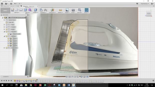
At this point, you have a theoretically printable 3D model. But in most cases, it needs some extra alterations to create a fully functioning model from the scan. Exact hole diameters, accurate parting line cut-offs and other critical features found in the Decomposition step of this complete process might need extra attention in order to have a viable model ready to be sent to the printer.
In this case, it is useful to import the model into a CAD modeling software program. In particular, Autodesk Fusion 360 is a very nice partner to Remake, as it is from the same company. Remake already has particular exporting settings for Fusion 360. After cleaning up as much as possible, error checking, and scaling—export your model for Fusion 360 to .OBJ (Quads). This will take some time. Importing this model into Fusion 360 and converting it to a T-spline solid in there results in an editable, solid shape onto which you can make dimensioned alterations, similar to what you would be able to do when modeling from scratch.
Open a new project in Fusion 360 and import the newly saved quad mesh under Insert > Mesh. Under the Sculpt options, find Convert and convert the imported mesh to a T-spine. Now you can go ahead and orientate the scan to a convenient orientation within the modeling environment and start modeling alterations.
CAD modeling is described further in another guide of this series. Or proceed on to Phase 3: Reproduction.

Team

iFixit, Team S1-G1, Weber Summer 2018 Membro di iFixit, Team S1-G1, Weber Summer 2018
FIX-WEBER-SU18S1G1
5 Membri
45 Guide realizzate
0 Commenti