
The power light never lights up.
@oldturkey03 I have possibly the same issue. I have the 12V 1A supply from my other Yamaha that I expect should work. The previous owner did not have the power supply and stated she tried to plug in one from something else. The power light never lights up.
My board looks identical but shows YM752 instead of YJ422. Do you know the difference between them? I can't find anything on the YM752.
I have to hold down the power button to get any power to come through. If I do this, I measure about 11V at test point 1. I have 4.95V at test point 2. Test points 3, 4, and 5 all show only .13V. This indicates that IC26, IC24, and IC2 would all be bad on the DM board. However, I don't know if that is the case since the board number is different. Any advice here is greatly appreciated. I don't want to order a YJ422 board and have it not work. Or a new YM752 and have that not be the issue even.
Update (10/01/24)
@oldturkey03 The test procedure above states it is for "No power indicator with power switch on". I have no power indicator so I followed that procedure. The board with the switch is only a simple button and all the controls are back on the DM board.
Now, the YM752 that is in mine can be found online and is listed for the P125. I see that the YJ422 is listed for the P128 online. However, the service manual, it shows that the YJ422 should be in the P125 so this is why I am confused. The boards look identical from what I can see, but I expect the P125 and P128 must have different programming.
In the manual, the JK board shows mosfet Q104. Mine does not have this component at all. There is a place for it but just nothing there. R104 is also missing as well as a bunch of other components shown. My model is just P125B but I see the ones in the service manual are listed as P125B/P and others. I expect they are a bit different. It is all rather confusing.


Questa è una buona domanda?
@jedwin90805 this "have to hold down the power button" sounds like either a bad mosfet or a bad relay. My money is on the mosfet. If you can post some well focused pictures of your board (both sides), so we can see what you get there. You would have to post it as an answer. Once it's posted. I'll move your comment etc. and your new answer to its own question. Let's see if we can figure this out.
da oldturkey03
@jedwin90805 look at the schematic vs the board layout. In the schematic on Q104 you see the annotation " no_use" that means it was never populated. This happens quite often with circuit boards. As the R&D continues once the board is developed, circuits are re-designed and make some of the components unnecessary. The same is most likely happening to the other components as well.
I do want you to check the voltage on D111 and the fuse TH101. Let's see if your board gets the full power from the DC-in jack. D111 is on the positive rail and TH101 on the negative. So, for D111 red probe to diode black to ground. The opposite for TH101
da oldturkey03
@oldturkey03 Measuring both of those locations I see 11.61V. I actually did that first, thinking one of those components could be burnt out. Power goes through the input board just fine though as long as the button is down.
If I measure at the connector CB101, I have nothing. If I hold down the power button, then I measure 11V at that point. This is the input power to the DM board. This can also be measured at the +B point. The test procedure just calls for more than 10V so that all seems ok. But again, only while holding down the button.
The power switch is only a momentary contact here that triggers something in the DM board to turn on. That isn't happening. The cable from this board goes back to the DM board at CB30. It looks like there is no relay, just a trigger to the logic section of the DM board. It has a "sleep" function rather than an actual power off. It looks like power should always be to those points even if it is in sleep mode.
da J Edwin
@jedwin90805 yes it should for as long as whatever the power switch turns on, stays on, which makes me think that Q101 as the switching regulator maybe the issue here. You ok with checking it? Here is the datasheet https://www.alldatasheet.com/datasheet-p...
da oldturkey03
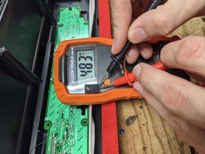
@oldturkey03 I had to take Q101 out of the board to make sure something wasn't going on with some other component in the board. Hopefully I am testing this properly like other mosfets.
I first shorted Gate to Drain for a few seconds which should open the connection from Drain to Source it until voltage is applied to the Gate. From Drain to Source I measure .485 without ever applying voltage to the Gate. D to S never opens and always stays at this value. I'll edit the original post and I think I can add the image that way.
da J Edwin