Salta al contenuto principale

Model A1312 / Mid 2010 / 3.2 GHz Core i3 or 2.8 & 3.6 GHz Core i5 or 2.93 GHz Core i7, ID iMac11,3

382 Domande Visualizza tutte

I need to run 2 jumper wires from my LVDS connector on my logic board.

Block Image

I have 2 missing copper pads under pins 3 and 6 where my LVDS connector mounts to my logic board. I have seen some videos where folks run jumper wires when this happens. If this is the correct way to proceed I need help finding where they need to go. I have the schematic for my computer and have pictures with red ovals next to the relevant information.

Block Image

Above is the LVDS connector schematic.

Block Image

This is where I believe pin 3 is supposed to go.

Block Image

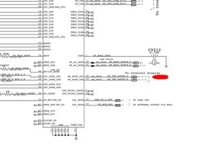
This is where I believe pin 6 is supposed to go.

Is it possible to run jumper wires from pins 3 and 6 of the new LVDS connector to where I have indicated on the schematics? If so, how do I find the locations with the red ovals on pictures 2 and 3 to run the jumper wires to?

Any help would be greatly appreciated.

Thanks

Risposto! Visualizza la risposta Anch'io ho questo problema

Questa è una buona domanda?

Punteggio 0
Aggiungi un commento

2 Risposte

Soluzione Prescelta

admarshall13  820-2901 is the correct board. Yours is actually straightforward to repair. Just apply jumpers from the solder pads to the point shows on the images. Do that after you resolder the connector

Block Image

Block Image

Block Image

Questa risposta è stata utile?

Punteggio 5

3 Commenti:

Thank you very much! I just want to make sure I understand you correctly. The small circles adjacent to the LVDS J9002 connector are what I solder the jumper wires to? So I bend up the 2 pins that correspond to the 2 missing pads, solder a jumper wire to each, and then solder the other ends to the small circles adjacent to the missing pads? What is the best way to solder the jumper to the small circle? Thanks again!

da

Yes that is the way you can do it. You do not need any pins bend. solder your connector back on then either solder a fine wire (I use strands from old LVDS cables) from the point to the pin on the connector that would normally soldered to the pad. No need to bend it.

da

Perfect. Thank you!

da

Aggiungi un commento

What you need is the Board View file and the app so you can trace out what is the closest point to jump the line to.

Locate your board number and preface boardview and the number in a Google search.

Questa risposta è stata utile?

Punteggio 4

6 Commenti:

Please have patience. I believe I have the board number, 820-2901-a, but don’t understand what “preface boardview and the number in a Google search” means. I searched “boadview 820-2901-a“ and did not come up with an obvious answer. I assume this has more to do with my lack of familiarity with what a board view file even looks like. I found multiple sites with various files with A1312 2390(model information) and 820-2901-a in the names. Not 1 distinct filename on multiple sites. All of these sites wanted me to pay $50-100 for access to the variously named files without letting me preview the document. I can understand if I need to pay for this but need to be sure I am getting the right document. Any further help or other resources would be much appreciated.

da

I went there and it is listed as laptop boardview. This is for a 27” iMac Desktop A1312 3.2 mid 2010. Also the number I found for my logic board was 820-2901-a. The files at the URL you shared do not have the “-a” at the end. I just want to make sure I am getting the right files before I spend money. Thanks for getting back to me Dan!

da

The -a is not important here.

da

That it is listed as a laptop not a desktop, does that matter either? Thanks again Dan.

da

Mostra 1 altro commento

Aggiungi un commento

Aggiungi la tua risposta

admarshall13 sarà eternamente grato.
Visualizza Statistiche:

Ultime 24 Ore: 0

Ultimi 7 Giorni: 1

Ultimi 30 Giorni: 7

Tutti i Tempi: 1,048