Salta al contenuto principale

Questa versione può contenere modifiche errate. Passa all'ultima istantanea verificata.

Cosa ti serve

  1. , Gruppo dello schermo: passo 1, immagine 1 di 3 , Gruppo dello schermo: passo 1, immagine 2 di 3 , Gruppo dello schermo: passo 1, immagine 3 di 3
    • Se il tuo vetro è in pezzi, evita di romperlo ulteriormente e di tagliarti con le schegge coprendolo con del nastro adesivo.

    • Applica delle strisce di nastro adesivo trasparente da pacchi sul vetro, una sopra l'altra, finché è completamente coperto.

    • Ciò conterrà le schegge di vetro e manterrà l'integrità strutturale quando dovrai fare leva e sollevare lo schermo.

    • Fai del tuo meglio per seguire il resto della guida come descritto. Comunque, una volta rotto il vetro, continuerà a rompersi mentre ci lavori e potresti dover usare uno strumento di apertura in metallo per rimuovere il vetro.

    • Indossa degli occhiali protettivi per proteggere gli occhi e stai attento a non danneggiare il pannello LCD.

  2. : passo 2, immagine 1 di 2 : passo 2, immagine 2 di 2
    • In questa guida dovrai fare leva sul gruppo dello schermo per rimuoverlo dalla scocca in alluminio. Segui le indicazioni attentamente per evitare di danneggiare lo schermo o i delicati ganci che lo tengono fermo.

    • Ci sono 14 clip in metallo che tengono fermo lo schermo, mostrati a sinistra. Mentre fai leva nei prossimi passaggi, cerca di fare forza attorno a questi e non cercare di passarci attraverso con il tuo strumento di apertura.

    • Se rompi qualche gancio, puoi comprarne di ricambio qui.

  3. : passo 3, immagine 1 di 2 : passo 3, immagine 2 di 2
    • Infila uno spudger di metallo tra il bordo superiore del gruppo dello schermo e la scocca.

    • Ruota lo spudger lontano da te per sganciare le clip lungo il bordo superiore dello schermo.

    • Infila un secondo spudger di metallo tra il bordo superiore dello schermo e la scocca per evitare che i ganci si richiudano.

  4. : passo 4, immagine 1 di 2 : passo 4, immagine 2 di 2
    • Con uno spudger, procedi lungo il bordo destro dell'iPad.

    • Lo schermo è tenuto fermo dai ganci metallici lungo i bordi superiore, inferiore e sinistro. Il bordo destro ha delle clip in plastica che fanno presa direttamente sulla scocca.

    • Una volta rilasciati i ganci, solleva il bordo sinistro dello schermo e fallo scorrere verso sinistra per liberare i ganci dalla scocca in alluminio.

    • Fai leva attentamente e delicatamente: se senti della resistenza, fermati e cambia posizione.

  5. : passo 5, immagine 1 di 1
    • Solleva il bordo inferiore del gruppo dello schermo dalla scocca .

    • Non cercare di rimuovere lo schermo a questo punto: è ancora collegato alla scheda madre.

  6. : passo 6, immagine 1 di 1
    • Nei prossimi passaggi dovrai scollegare i tre cavi che collegano il gruppo dello schermo alla scheda madre. I cavi sono per le seguenti componenti:

    • Digitizer

    • Sensore di luce ambientale

    • Cavo dati dello schermo

  7. : passo 7, immagine 1 di 3 : passo 7, immagine 2 di 3 : passo 7, immagine 3 di 3
    • Usa la punta di uno strumento di apertura in plastica per girare verso l'alto le alette di bloccaggio che tengono fermo i cavi del digitizer nelle loro prese sulla scheda madre.

    • Assicurati di far leva sull'aletta e non sul connettore.

    • Sfila i cavi a nastro del digitizer dalle loro prese.

  8. : passo 8, immagine 1 di 1
    • Usa uno strumento di apertura in plastica per scollegare il connettore del sensore di luce ambientale dalla sua presa sulla scheda madre facendo una leggera leva verso l'alto.

  9. : passo 9, immagine 1 di 2 : passo 9, immagine 2 di 2
    • Scollega il cavo dati dello schermo dalla scheda madre ribaltando la staffa in metallo di bloccaggio tirandola dalla sua linguetta in plastica.

    • Sfila il connettore del cavo dalla sua presa.

    • Tira il connettore parallelamente al piano della scheda madre.

  10. : passo 10, immagine 1 di 1
    • Rimuovi il gruppo dello schermo dalla scocca.

  11. Questo passaggio è privo di traduzione. Aiuta a tradurlo

    : passo 11, immagine 1 di 3 : passo 11, immagine 2 di 3 : passo 11, immagine 3 di 3
    • If you are reusing the LCD, it is not necessary to peel the ambient light sensor off the back face of the LCD.

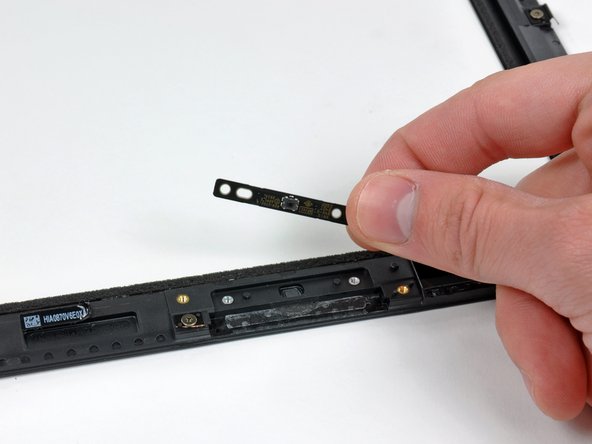
    • Use the edge of a plastic opening tool to carefully pry the ambient light sensor board off the adhesive securing it to the display frame.

    • Once you've gained enough clearance, peel the ambient light sensor off the LCD.

    • Be careful not to crease the ambient light sensor below its top section, as the portion with adhesive applied may break off.

    • If necessary, attach the plastic view window to your new ambient light sensor before installation.

  12. Questo passaggio è privo di traduzione. Aiuta a tradurlo

    : passo 12, immagine 1 di 1
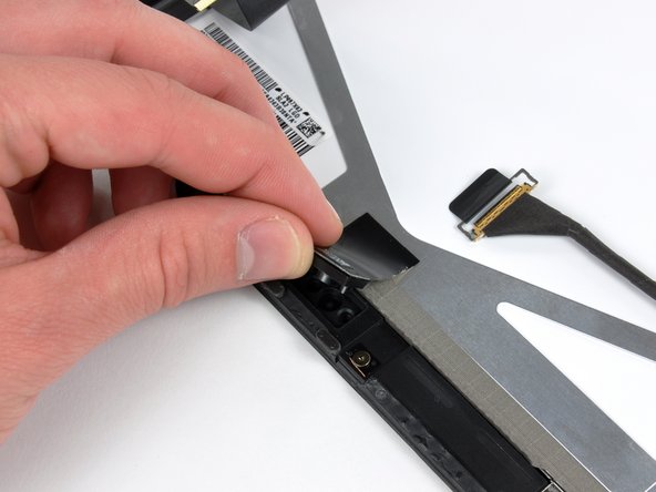
    • While holding the digitizer cable down, carefully peel back the piece of tape connecting the digitizer cable to the display frame.

  13. Questo passaggio è privo di traduzione. Aiuta a tradurlo

    : passo 13, immagine 1 di 2 : passo 13, immagine 2 di 2
    • Remove the three T5 Torx screws securing the clips and LCD brackets covered in EMI tape near the home button switch.

    • Carefully peel the display clip and its attached tape off the black plastic display frame.

    • If you are replacing the LCD, be sure to transfer these pieces of EMI tape and their attached clips to the new LCD.

  14. Questo passaggio è privo di traduzione. Aiuta a tradurlo

    : passo 14, immagine 1 di 1
    • Remove the remaining T5 Torx screws securing the LCD to the black plastic display frame.

  15. Questo passaggio è privo di traduzione. Aiuta a tradurlo

    : passo 15, immagine 1 di 2 : passo 15, immagine 2 di 2
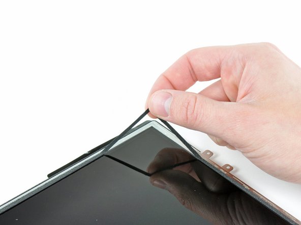
    • Insert the edge of a plastic opening tool under one of the ears attached to the steel LCD frame.

    • Twist the plastic opening tool to gently pry the LCD up off the adhesive securing it to the front glass panel.

    • Be sure not to excessively bend the LCD, as it is made of glass.

  16. Questo passaggio è privo di traduzione. Aiuta a tradurlo

    : passo 16, immagine 1 di 1
    • Repeat the process detailed on the previous step to pry up the display around the three sides opposite the digitizer cable side of the display.

  17. Questo passaggio è privo di traduzione. Aiuta a tradurlo

    : passo 17, immagine 1 di 2 : passo 17, immagine 2 di 2
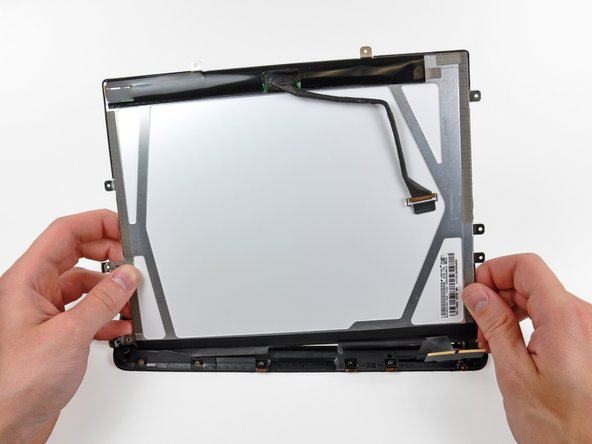
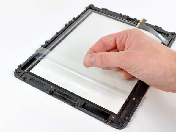
    • Lift the LCD from its free end, and remove it from the display frame.

    • Carefully peel the adhesive securing the long side of the LCD to the display frame, then remove the LCD.

  18. Questo passaggio è privo di traduzione. Aiuta a tradurlo

    : passo 18, immagine 1 di 1
    • If it is still stuck to the front panel, remove the strip of EMI tape near the ambient light sensor socket.

    • If necessary, transfer this to your new LCD.

    • If it is attached to the LCD and you are reusing the LCD, skip this step. If you are replacing the LCD as well, transfer the strip of EMI tape to your new LCD.

  19. Questo passaggio è privo di traduzione. Aiuta a tradurlo

    : passo 19, immagine 1 di 1
    • If they are still in good shape, transfer the clips and EMI tape near the bottom of the LCD to your new LCD.

  20. Questo passaggio è privo di traduzione. Aiuta a tradurlo

    : passo 20, immagine 1 di 2 : passo 20, immagine 2 di 2
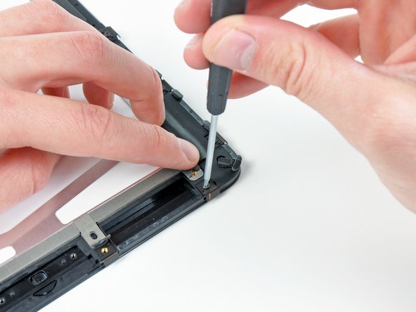
    • Remove the two T5 Torx screws securing the home button switch to the plastic display frame.

    • Remove the home button switch board from the front panel assembly.

  21. Questo passaggio è privo di traduzione. Aiuta a tradurlo

    : passo 21, immagine 1 di 2 : passo 21, immagine 2 di 2
    • If you are reusing your LCD, use the edge of a plastic opening tool to lift up a corner of the foam tape attached to the LCD.

    • Remove the tape from the perimeter of the glass face of the LCD.

  22. Questo passaggio è privo di traduzione. Aiuta a tradurlo

    : passo 22, immagine 1 di 2 : passo 22, immagine 2 di 2
    • Remove the piece of yellow tape securing the digitizer cable to the inner face of the front panel assembly, being careful not to rip the cable in the process.

    • Peel the protective sheeting off the inner face of the front panel assembly.

    • Be careful not to get any fingerprints or dust on the inner face of the front panel, as they will be annoyingly visible when the device is turned on.

  23. Questo passaggio è privo di traduzione. Aiuta a tradurlo

    : passo 23, immagine 1 di 1
    • Be sure the face of the LCD is perfectly clean before proceeding.

    • Stick the tape down along the long edge of the LCD to the frame of the front panel assembly.

    • Carefully lower the LCD down into its recess in the front panel frame, being sure it is properly positioned.

  24. Questo passaggio è privo di traduzione. Aiuta a tradurlo

    : passo 24, immagine 1 di 3 : passo 24, immagine 2 di 3 : passo 24, immagine 3 di 3
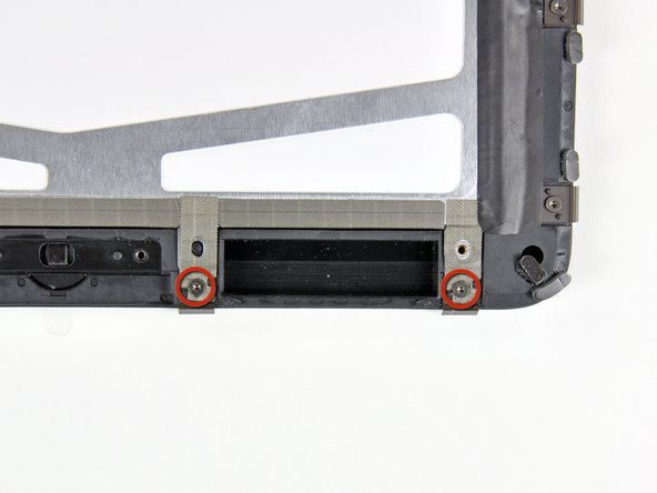
    • Hold back the strips of EMI tape along the lower edge of the LCD as you remove the two T5 Torx screws securing the retaining clips shown.

    • Stick the tape down against the new clips and reinstall the two T5 Torx screws.

    • If you are replacing your panel with a new one, be aware that the new panel may have a protective film on the outside and/or inside of the frame. This needs to be removed.

Linea Traguardo

Altre 44 persone hanno completato questa guida.

Un commento

LCD cable is easily trapped under lcd on reassembly without due care causing colour differences on snapping into place

scott corbett - Replica

Aggiungi Commento

Visualizza Statistiche:

Ultime 24 Ore: 4

Ultimi 7 Giorni: 21

Ultimi 30 Giorni: 41

Tutti i Tempi: 59,473