Questa versione può contenere modifiche errate. Passa all'ultima istantanea verificata.
Cosa ti serve
-
Questo passaggio è privo di traduzione. Aiuta a tradurlo
-
Place the device on a flat surface, upside down, so the bottom of the screen would be facing upwards.
-
Remove the ten 3.5mm Phillips #0 screws from the back plate.
-
-
Questo passaggio è privo di traduzione. Aiuta a tradurlo
-
Use a plastic opening tool to remove the back plate.
-
-
Questo passaggio è privo di traduzione. Aiuta a tradurlo
-
Disconnect the USB cable from the display board.
-
-
Questo passaggio è privo di traduzione. Aiuta a tradurlo
-
Adjust the rubber holders that are keeping the USB cable still on the motherboard, so you can remove the cable entirely from the inner compartment.
-
-
Questo passaggio è privo di traduzione. Aiuta a tradurlo
-
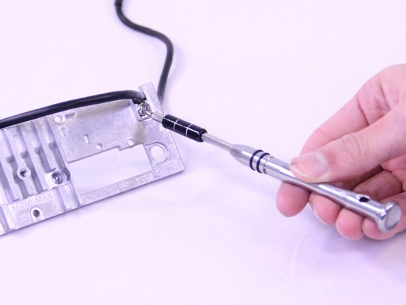
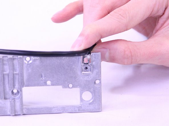
Remove the 3.5mm Phillip #0 screw that secures the USB cable to the back panel.
-
Pull the USB cable off of the back plate.
-
-
-
Questo passaggio è privo di traduzione. Aiuta a tradurlo
-
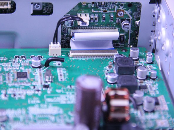
Disconnect the display power cable from the motherboard.
-
Use a spudger to flip up the retaining flap on the display ribbon cable ZIF socket.
-
-
Questo passaggio è privo di traduzione. Aiuta a tradurlo
-
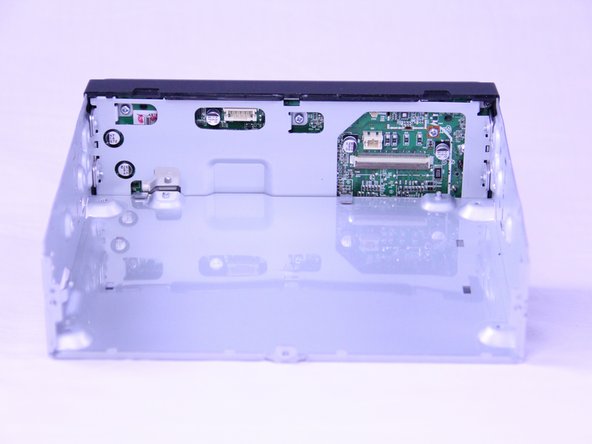
Unscrew the four 3.5mm Phillips #0 screws from the motherboard.
-
Use a spudger to gently lift the motherboard up and out of the radio.
-
-
Questo passaggio è privo di traduzione. Aiuta a tradurlo
-
Remove the four 3.5mm Phillips #0 screws from the sides of the display.
-
-
Questo passaggio è privo di traduzione. Aiuta a tradurlo
-
Remove two 3.5mm Phillips #0 screws from the back of the head unit.
-
-
Questo passaggio è privo di traduzione. Aiuta a tradurlo
-
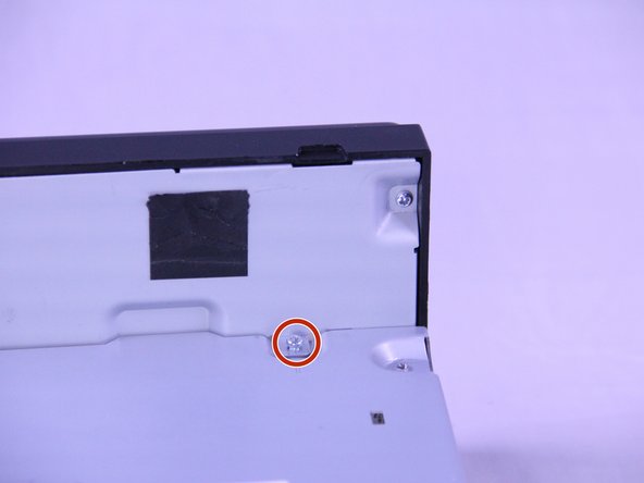
Remove the four 3.5mm Phillips #0 screws from the display board.
-
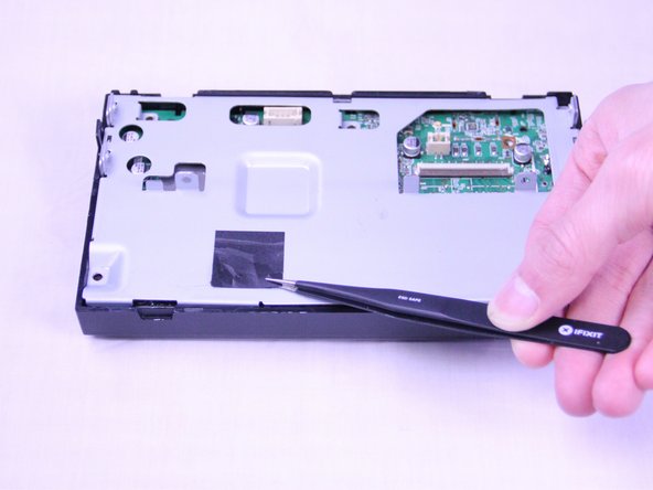
Remove the black tape using a precise tweezer.
-
Remove the 3.5mm Phillips #0 screw from underneath the tape.
-
-
Questo passaggio è privo di traduzione. Aiuta a tradurlo
-
Remove the two 2mm Phillips #0 screws from the back plate.
-
Remove the back plate.
-
-
Questo passaggio è privo di traduzione. Aiuta a tradurlo
-
Remove the single 2mm Phillips #0 screw from the motherboard.
-
Use a spudger to flip up the retaining flap on the display ribbon cable ZIF socket.
-
-
Questo passaggio è privo di traduzione. Aiuta a tradurlo
-
Use a plastic opening tool to remove the display board from the radio.
-


Annulla: non ho completato questa guida.
Un'altra persona ha completato questa guida.
Team

USF Tampa, Team S1-G5, Cagle Spring 2018 Membro di USF Tampa, Team S1-G5, Cagle Spring 2018
USFT-CAGLE-S18S1G5
2 Membri
5 Guide realizzate