Questa versione può contenere modifiche errate. Passa all'ultima istantanea verificata.
Cosa ti serve
-
Questo passaggio è privo di traduzione. Aiuta a tradurlo
-
Begin by opening the HDMI/USB port cover on the left edge.
-
Remove the three #000 headed, 3 mm long screws located underneath the port cover.
-
-
Questo passaggio è privo di traduzione. Aiuta a tradurlo
-
Locate and open the Micro SD slot on the top side of the device.
-
Remove the two screws located beneath the cover.
-
-
Questo passaggio è privo di traduzione. Aiuta a tradurlo
-
Attach the suction cup to the top right area of the screen.
-
Pull to separate the screen from the rest of the device.
-
Detach the display ribbon cable.
-
-
-
Questo passaggio è privo di traduzione. Aiuta a tradurlo
-
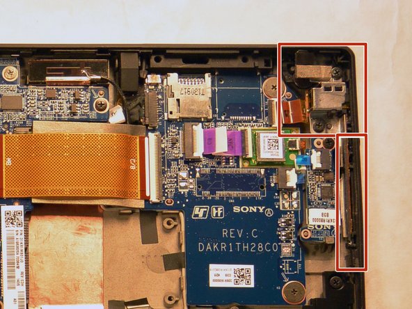
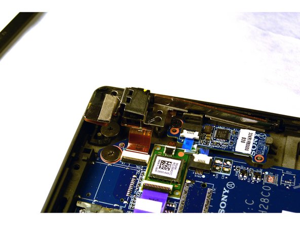
Once the battery is disconnected, locate the audio jack.
-
-
Questo passaggio è privo di traduzione. Aiuta a tradurlo
-
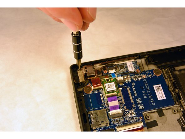
Using the Phillips #000, remove the two 3 mm screws.
-
-
Questo passaggio è privo di traduzione. Aiuta a tradurlo
-
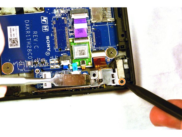
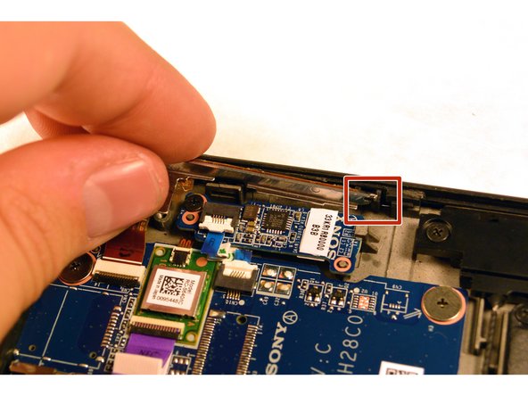
With the screws removed, use a plastic opening tool to lightly pry the board up over a plastic positioning peg.
-
Insert the tip of a spudger where the upper screw was located and push the board inward while prying up with the plastic opening tool.
-
Lightly pry with the opening tool, enough for the board to lift off the positioning peg and then push inward with the spudger. The board should begin to separate from the corner.
-
-
Questo passaggio è privo di traduzione. Aiuta a tradurlo
-
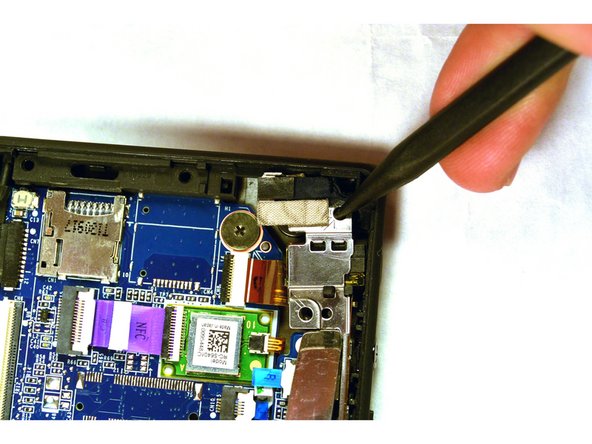
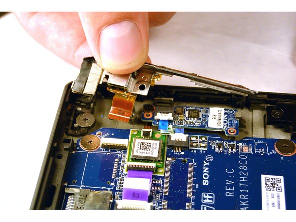
Remove the rest of the board by pulling it up and out.
-
Pull the small narrow end of the board horizontally towards the corner, freeing the board from the panel with the exception of the connector.
-
-
Questo passaggio è privo di traduzione. Aiuta a tradurlo
-
Disconnect the audio jack connector and remove the entire audio jack power volume button board assembly.
-


Annulla: non ho completato questa guida.
Altre 2 persone hanno completato questa guida.
Team

IUPUI, Team 1-2, Harley Fall 2015 Membro di IUPUI, Team 1-2, Harley Fall 2015
IUPUI-HARLEY-F15S1G2
4 Membri
20 Guide realizzate