Questa versione può contenere modifiche errate. Passa all'ultima istantanea verificata.
Cosa ti serve
-
Questo passaggio è privo di traduzione. Aiuta a tradurlo
-
Disconnect all power cords.
-
Remove the rubber foot and plastic screw guard on the bottom of the device using a plastic opening tool.
-
Note: the rubber foot and plastic screw guard can be removed as one piece to make reassembly easier
-
-
Questo passaggio è privo di traduzione. Aiuta a tradurlo
-
Remove the four 10mm Torx T10 screws from the bottom of the speaker.
-
-
Questo passaggio è privo di traduzione. Aiuta a tradurlo
-
Remove the bottom cover by squeezing the protective cover slightly while pushing up with your fingers.
-
-
Questo passaggio è privo di traduzione. Aiuta a tradurlo
-
Remove the single 8mm Torx T10 screw and protective cover clip.
-
-
Questo passaggio è privo di traduzione. Aiuta a tradurlo
-
Slide the protective cover upwards to remove.
-
-
Questo passaggio è privo di traduzione. Aiuta a tradurlo
-
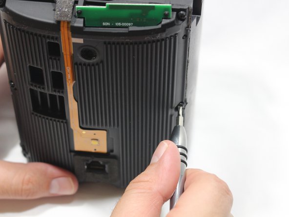
Remove the four 9mm Torx T8 screws from around the perimeter of the control panel.
-
-
-
Questo passaggio è privo di traduzione. Aiuta a tradurlo
-
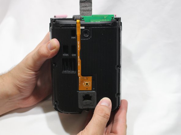
With the front of the unit facing you, lift the control panel up using your thumbs.
-
-
Questo passaggio è privo di traduzione. Aiuta a tradurlo
-
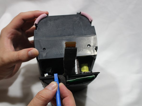
Use a spudger to flip up the retaining flap on the control panel ribbon cable ZIF socket.
-
Pull the control panel ribbon cable out of its socket.
-
-
Questo passaggio è privo di traduzione. Aiuta a tradurlo
-
Pull the control panel away from the speaker to separate.
-
-
Questo passaggio è privo di traduzione. Aiuta a tradurlo
-
Remove the six 9mm Torx T8 screws from the motherboard panel.
-
-
Questo passaggio è privo di traduzione. Aiuta a tradurlo
-
Using a plastic opening tool, separate the motherboard from the speaker.
-
-
Questo passaggio è privo di traduzione. Aiuta a tradurlo
-
Using your thumb, disconnect the speaker cable from the motherboard.
-
-
Questo passaggio è privo di traduzione. Aiuta a tradurlo
-
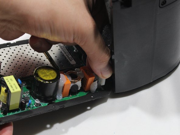
Disconnect the power adapter plug from the motherboard using your thumb.
-
-
Questo passaggio è privo di traduzione. Aiuta a tradurlo
-
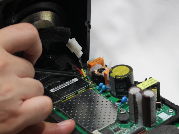
Using the pointed end of the spudger, disconnect the red, green, and yellow cables connecting the WiFi transmitter/receiver.
-
-
Questo passaggio è privo di traduzione. Aiuta a tradurlo
-
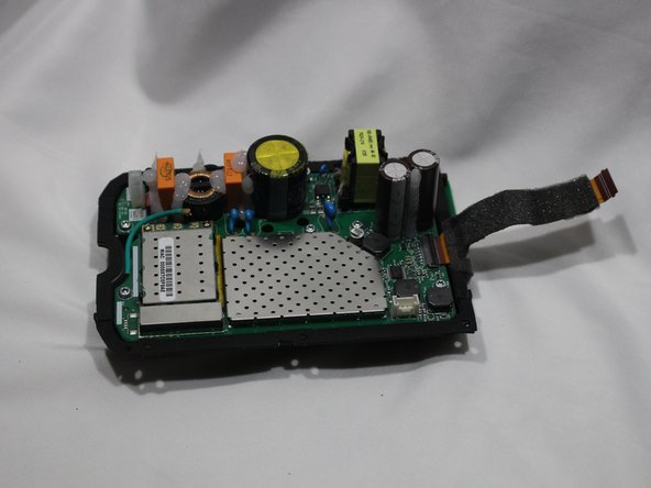
Remove the motherboard panel from the speaker housing.
-
-
Questo passaggio è privo di traduzione. Aiuta a tradurlo
-
Remove the two 9mm Torx T8 screws from the power adapter plug.
-
Remove the power adapter receptacle from its housing slot.
-


Annulla: non ho completato questa guida.
Altre 7 persone hanno completato questa guida.
Team

USF Tampa, Team S2-G1, Nance Spring 2018 Membro di USF Tampa, Team S2-G1, Nance Spring 2018
USFT-NANCE-S18S2G1
3 Membri
6 Guide realizzate