Questa versione può contenere modifiche errate. Passa all'ultima istantanea verificata.
Cosa ti serve
-
Questo passaggio è privo di traduzione. Aiuta a tradurlo
-
Rotate the phone onto its front side so that the LCD screen is facing away from you.
-
-
Questo passaggio è privo di traduzione. Aiuta a tradurlo
-
Remove the battery by pressing down on the battery release button while sliding the battery downwards.
-
-
Questo passaggio è privo di traduzione. Aiuta a tradurlo
-
Remove the four small black screws that secure the back phone panel using the Phillips #00 screwdriver.
-
-
Questo passaggio è privo di traduzione. Aiuta a tradurlo
-
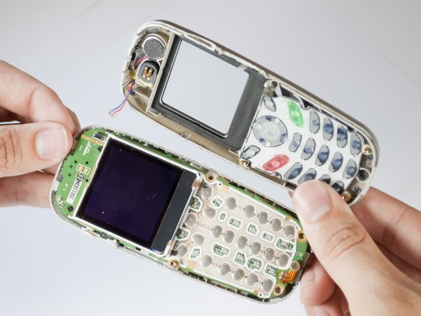
Carefully separate the front and back panels by gently prying them apart. Start at the bottom of the phone (near the AC charger input).
-
-
-
Questo passaggio è privo di traduzione. Aiuta a tradurlo
-
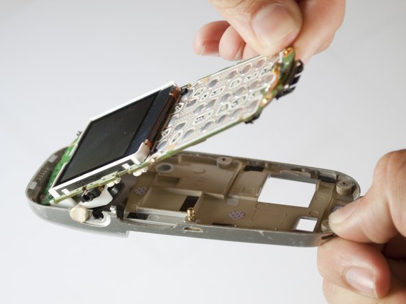
Using your nails, tweezers, or any precise grabbing tool, pinch the antenna wire connector (clear plastic plug) and pull gently. It should pop out rather easily.
-
-
Questo passaggio è privo di traduzione. Aiuta a tradurlo
-
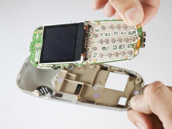
Gently remove the logic board and LCD screen from the back cover of the phone.
-
-
Questo passaggio è privo di traduzione. Aiuta a tradurlo
-
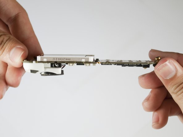
Remove the two screws above the LCD screen with a Phillips #00 screw driver. These connect to the white plastic cover in which the speaker is housed located on the reverse side of the logic board.
-
-
Questo passaggio è privo di traduzione. Aiuta a tradurlo
-
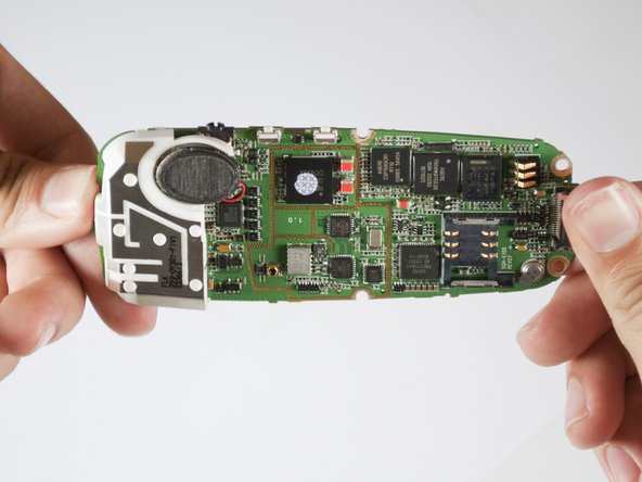
Rotate the logic board so that the LCD screen is face down.
-
-
Questo passaggio è privo di traduzione. Aiuta a tradurlo
-
Gently begin to separate the white plastic cover from the logic board.
-
-
Questo passaggio è privo di traduzione. Aiuta a tradurlo
-
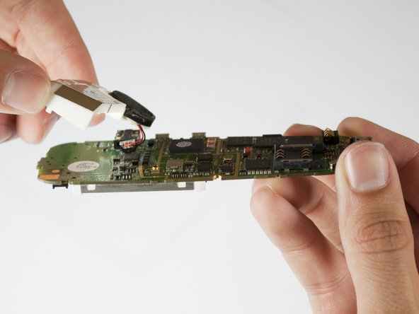
Locate the two wires (black and red) which connect the speaker to the logic board.
-
Using your nails, tweezers, or any precise grabbing tool, pinch the speaker connector (clear plastic plug that goes into the logic board) and pull gently. It should pop out easily.
-
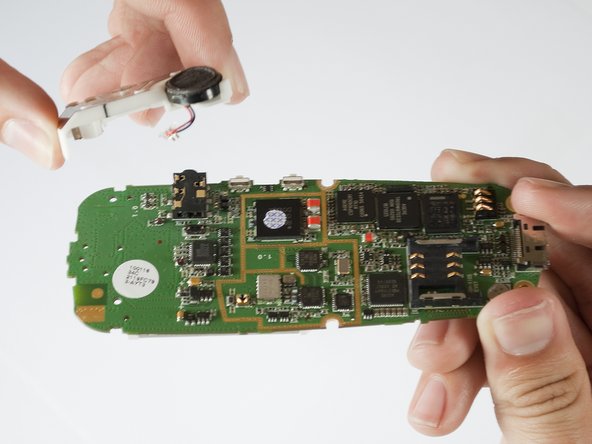
Once the wires are disconnected and the screws removed, the white plastic cover can easily be removed from the logic board.
-


Team

Cal Poly, Team 28-29, Regan Spring 2010 Membro di Cal Poly, Team 28-29, Regan Spring 2010
CPSU-REGAN-S10S28G29
4 Membri
12 Guide realizzate