Questa versione può contenere modifiche errate. Passa all'ultima istantanea verificata.
Cosa ti serve
-
Questo passaggio è privo di traduzione. Aiuta a tradurlo
-
Eject the disk tray from the DVD player before removing power supply.
-
-
Questo passaggio è privo di traduzione. Aiuta a tradurlo
-
Evenly lift upward on the disk tray front cover (not slanted, as pictured). This will allow for easier disassembly of the player.
-
-
Questo passaggio è privo di traduzione. Aiuta a tradurlo
-
Remove the three screws running along the back edge of case cover.
-
Remove the two screws from each side of the case cover.
-
-
-
Questo passaggio è privo di traduzione. Aiuta a tradurlo
-
Grab edges of the cover with your hands. Pull outward slightly, then straight up.
-
-
Questo passaggio è privo di traduzione. Aiuta a tradurlo
-
Lift up the five tabs securing the front panel to the chassis. There are three on the bottom, and two on the inside edges of the panel. Panel should then lift off the player.
-
-
Questo passaggio è privo di traduzione. Aiuta a tradurlo
-
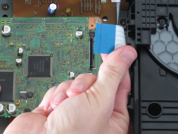
Remove the blue ribbon wire from its connector. When doing this, be cautious to not damage the connector.
-
Place forefinger under cable loop as shown, gripping with thumb.
-
Pull straight up. It should disconnect with little force.
-
-
Questo passaggio è privo di traduzione. Aiuta a tradurlo
-
Using tweezers or pliers, squeeze the tabs of the plastic fasteners together. While doing this, gently lift up on the motherboard until the fasteners are released.
-
-
Questo passaggio è privo di traduzione. Aiuta a tradurlo
-
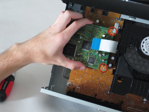
Remove the two screws securing the motherboard using a philips screw driver.
-
-
Questo passaggio è privo di traduzione. Aiuta a tradurlo
-
Lift the board from the side closest to the front panel (top of photo).
-
Gently apply force until bottom connector releases from power board below.
-


Annulla: non ho completato questa guida.
Un'altra persona ha completato questa guida.
Team

Cal Poly, Team 18-20, Garner Spring 2011 Membro di Cal Poly, Team 18-20, Garner Spring 2011
CPSU-GARNER-S11S18G20
4 Membri
11 Guide realizzate