Salta al contenuto principale

PowerBook G4 Aluminum 17" 1.67 GHz (High-Res) Heat Sink & Fan Assembly Replacement

Cosa ti serve

  1. PowerBook G4 Aluminum 17" 1.67 GHz (High-Res) Heat Sink & Fan Assembly Replacement, Battery: passo 1, immagine 1 di 2 PowerBook G4 Aluminum 17" 1.67 GHz (High-Res) Heat Sink & Fan Assembly Replacement, Battery: passo 1, immagine 2 di 2
    • Use your thumbs to push the two battery retaining tabs away from the battery.

    • The battery should pop up enough to rotate it toward yourself and lift it out of the lower case.

  2. PowerBook G4 Aluminum 17" 1.67 GHz (High-Res) Heat Sink & Fan Assembly Replacement, Memory Door: passo 2, immagine 1 di 1
    • Remove the three 2.3 mm Phillips screws securing the memory cover to the lower case.

  3. PowerBook G4 Aluminum 17" 1.67 GHz (High-Res) Heat Sink & Fan Assembly Replacement: passo 3, immagine 1 di 2 PowerBook G4 Aluminum 17" 1.67 GHz (High-Res) Heat Sink & Fan Assembly Replacement: passo 3, immagine 2 di 2
    • Lift the memory cover slightly and pull it toward yourself to remove it from the lower case.

  4. PowerBook G4 Aluminum 17" 1.67 GHz (High-Res) Heat Sink & Fan Assembly Replacement, Upper Case: passo 4, immagine 1 di 1
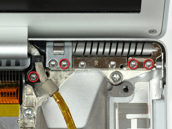
    • Remove the following ten screws:

    • Two 14.7 mm shouldered Phillips.

    • Three 12.3 mm Phillips.

    • One 3.8 mm T8 Torx.

    • One 6.8 mm T8 Torx.

    • Three 1.3 mm Phillips.

  5. PowerBook G4 Aluminum 17" 1.67 GHz (High-Res) Heat Sink & Fan Assembly Replacement: passo 5, immagine 1 di 2 PowerBook G4 Aluminum 17" 1.67 GHz (High-Res) Heat Sink & Fan Assembly Replacement: passo 5, immagine 2 di 2
    • The ZIF cable is located underneath the bottom RAM slot. If your PowerBook has both RAM slots occupied, make sure to remove the RAM chip.

    • Use your fingernails to separate the ZIF cable lock away from its socket. (Move the two brown bits down 1mm)

    • The ZIF cable lock will move about a millimeter away from the socket before it stops (see picture 2). Do not try to remove the ZIF cable lock.

  6. PowerBook G4 Aluminum 17" 1.67 GHz (High-Res) Heat Sink & Fan Assembly Replacement: passo 6, immagine 1 di 1
    • Use the tip of a spudger to slide the trackpad ribbon cable out of its socket.

  7. PowerBook G4 Aluminum 17" 1.67 GHz (High-Res) Heat Sink & Fan Assembly Replacement: passo 7, immagine 1 di 1
    • Remove the four 3.4 mm Phillips screws from the PC card side of the PowerBook.

    • When replacing these screws, you must reinstall each screw in the correct order. Begin by installing the screw closest to the display hinge, and go out from there.

  8. PowerBook G4 Aluminum 17" 1.67 GHz (High-Res) Heat Sink & Fan Assembly Replacement: passo 8, immagine 1 di 1
    • Remove the four 3.4 mm Phillips screws from the DVI connector side of the PowerBook.

    • When replacing these screws, you must reinstall each screw in the correct order. Begin by installing the screw closest to the display hinge, and go out from there.

    • During reassembly, make sure to reinstall the two screws on the right into their appropriate locations, and not the DVI port anchor holes.

  9. PowerBook G4 Aluminum 17" 1.67 GHz (High-Res) Heat Sink & Fan Assembly Replacement: passo 9, immagine 1 di 2 PowerBook G4 Aluminum 17" 1.67 GHz (High-Res) Heat Sink & Fan Assembly Replacement: passo 9, immagine 2 di 2
    • Depress the display latch release button and open your display.

  10. PowerBook G4 Aluminum 17" 1.67 GHz (High-Res) Heat Sink & Fan Assembly Replacement: passo 10, immagine 1 di 2 PowerBook G4 Aluminum 17" 1.67 GHz (High-Res) Heat Sink & Fan Assembly Replacement: passo 10, immagine 2 di 2
    • Starting near the display, lift the upper case straight up off the lower case, minding any cables that may get caught.

  11. PowerBook G4 Aluminum 17" 1.67 GHz (High-Res) Heat Sink & Fan Assembly Replacement, Speakers: passo 11, immagine 1 di 1
    • Disconnect the RJ-11 cable from the modem.

  12. PowerBook G4 Aluminum 17" 1.67 GHz (High-Res) Heat Sink & Fan Assembly Replacement: passo 12, immagine 1 di 1
    • If necessary, remove the strip of tape covering the speaker cables.

  13. PowerBook G4 Aluminum 17" 1.67 GHz (High-Res) Heat Sink & Fan Assembly Replacement: passo 13, immagine 1 di 2 PowerBook G4 Aluminum 17" 1.67 GHz (High-Res) Heat Sink & Fan Assembly Replacement: passo 13, immagine 2 di 2
    • Use your fingernails or the tip of a spudger to separate the ZIF cable lock from its socket.

    • The ZIF cable lock will move about 1 mm and stop. Do not attempt to completely remove the ZIF cable lock.

  14. PowerBook G4 Aluminum 17" 1.67 GHz (High-Res) Heat Sink & Fan Assembly Replacement: passo 14, immagine 1 di 1
    • Pull the DC-in ribbon cable straight away from its socket.

  15. PowerBook G4 Aluminum 17" 1.67 GHz (High-Res) Heat Sink & Fan Assembly Replacement: passo 15, immagine 1 di 1
    • Peel the DC-in cable off the adhesive securing it to the lower case.

  16. PowerBook G4 Aluminum 17" 1.67 GHz (High-Res) Heat Sink & Fan Assembly Replacement: passo 16, immagine 1 di 2 PowerBook G4 Aluminum 17" 1.67 GHz (High-Res) Heat Sink & Fan Assembly Replacement: passo 16, immagine 2 di 2
    • If necessary, use the tip of a spudger to remove the small piece of foam tape from the side of the left speaker.

    • De-route the AirPort antenna cables from the channel in the left speaker.

  17. PowerBook G4 Aluminum 17" 1.67 GHz (High-Res) Heat Sink & Fan Assembly Replacement: passo 17, immagine 1 di 1
    • Remove the single 6.9 mm T8 Torx screw securing the left speaker to the lower case.

  18. PowerBook G4 Aluminum 17" 1.67 GHz (High-Res) Heat Sink & Fan Assembly Replacement: passo 18, immagine 1 di 2 PowerBook G4 Aluminum 17" 1.67 GHz (High-Res) Heat Sink & Fan Assembly Replacement: passo 18, immagine 2 di 2
    • Lift the left speaker from its rear edge and maneuver it out of the lower case, minding the cables sitting in the channel near the front edge of the left speaker.

  19. PowerBook G4 Aluminum 17" 1.67 GHz (High-Res) Heat Sink & Fan Assembly Replacement: passo 19, immagine 1 di 1
    • Remove the single 6.9 mm T8 Torx screw securing the speaker cable ground loop to the lower case.

  20. PowerBook G4 Aluminum 17" 1.67 GHz (High-Res) Heat Sink & Fan Assembly Replacement: passo 20, immagine 1 di 1
    • Peel back the piece of foil tape covering the modem cable to free the speaker cable held underneath.

  21. PowerBook G4 Aluminum 17" 1.67 GHz (High-Res) Heat Sink & Fan Assembly Replacement: passo 21, immagine 1 di 1
    • Pull the speaker cable straight up to disconnect it from the sound card.

  22. PowerBook G4 Aluminum 17" 1.67 GHz (High-Res) Heat Sink & Fan Assembly Replacement: passo 22, immagine 1 di 1
    • In the next few steps, you will disconnect several ribbon cables that cover the right speaker cable.

    • Use the flat end of a spudger to pry the hard drive ribbon cable connector up off the logic board.

  23. PowerBook G4 Aluminum 17" 1.67 GHz (High-Res) Heat Sink & Fan Assembly Replacement: passo 23, immagine 1 di 1
    • Use the flat end of a spudger to pry the sound card cable connector up off the logic board.

  24. PowerBook G4 Aluminum 17" 1.67 GHz (High-Res) Heat Sink & Fan Assembly Replacement: passo 24, immagine 1 di 1
    • Use the flat end of a spudger to pry the optical drive cable connector up off the logic board.

  25. PowerBook G4 Aluminum 17" 1.67 GHz (High-Res) Heat Sink & Fan Assembly Replacement: passo 25, immagine 1 di 2 PowerBook G4 Aluminum 17" 1.67 GHz (High-Res) Heat Sink & Fan Assembly Replacement: passo 25, immagine 2 di 2
    • Use your fingernails or the tip of a spudger to separate the ZIF cable lock from its socket.

    • The ZIF cable lock will move about 1 mm and stop. Do not attempt to completely remove the ZIF cable lock.

  26. PowerBook G4 Aluminum 17" 1.67 GHz (High-Res) Heat Sink & Fan Assembly Replacement: passo 26, immagine 1 di 1
    • Pull the PRAM battery & USB board cable out of its socket.

  27. PowerBook G4 Aluminum 17" 1.67 GHz (High-Res) Heat Sink & Fan Assembly Replacement: passo 27, immagine 1 di 1
    • Use a spudger to de-route the display data cable from the channel in the right speaker.

  28. PowerBook G4 Aluminum 17" 1.67 GHz (High-Res) Heat Sink & Fan Assembly Replacement: passo 28, immagine 1 di 1
    • Use the tip of a spudger to pry the power button LED window off the right speaker.

    • Try to place the window curved-side down on your work surface to keep the adhesive around its perimeter clean.

  29. PowerBook G4 Aluminum 17" 1.67 GHz (High-Res) Heat Sink & Fan Assembly Replacement: passo 29, immagine 1 di 1
    • Remove the single T8 6.9 mm Torx screw securing the right speaker to the lower case.

  30. PowerBook G4 Aluminum 17" 1.67 GHz (High-Res) Heat Sink & Fan Assembly Replacement: passo 30, immagine 1 di 1
    • Lift the right speaker out of the lower case.

  31. PowerBook G4 Aluminum 17" 1.67 GHz (High-Res) Heat Sink & Fan Assembly Replacement: passo 31, immagine 1 di 1
    • De-route the speaker cable from the clips along the front edge of the logic board.

    • The clips open in different directions, so be careful to not break any off during removal.

  32. PowerBook G4 Aluminum 17" 1.67 GHz (High-Res) Heat Sink & Fan Assembly Replacement, Logic Board: passo 32, immagine 1 di 1
    • Close your PowerBook, minding any cables that may interfere, and flip it over.

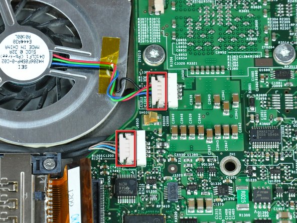
    • Disconnect the power cable connector by pulling it straight away from its socket on the logic board.

  33. PowerBook G4 Aluminum 17" 1.67 GHz (High-Res) Heat Sink & Fan Assembly Replacement: passo 33, immagine 1 di 1
    • Disconnect the battery cable connector straight away from its socket on the logic board.

  34. PowerBook G4 Aluminum 17" 1.67 GHz (High-Res) Heat Sink & Fan Assembly Replacement: passo 34, immagine 1 di 1
    • Use the flat end of a spudger to pry the AirPort/Bluetooth cable connector up off the logic board.

  35. PowerBook G4 Aluminum 17" 1.67 GHz (High-Res) Heat Sink & Fan Assembly Replacement: passo 35, immagine 1 di 1
    • Turn the PowerBook back over.

    • Use the flat end of a spudger to pry the modem cable connector up off the logic board.

  36. PowerBook G4 Aluminum 17" 1.67 GHz (High-Res) Heat Sink & Fan Assembly Replacement: passo 36, immagine 1 di 1
    • Use the flat end of a spudger to pry the PC card cage cable connector up off the logic board.

  37. PowerBook G4 Aluminum 17" 1.67 GHz (High-Res) Heat Sink & Fan Assembly Replacement: passo 37, immagine 1 di 1
    • Disconnect both of the following connectors from the logic board:

    • Left fan cable.

    • Inverter cable.

    • Be sure to pull only parallel to the face of the logic board, as pulling up on the socket will break it off the logic board.

    • When pulling these connectors away from their sockets, it is helpful to use your fingernails to pull on the ears at each side of the connector.

  38. PowerBook G4 Aluminum 17" 1.67 GHz (High-Res) Heat Sink & Fan Assembly Replacement: passo 38, immagine 1 di 2 PowerBook G4 Aluminum 17" 1.67 GHz (High-Res) Heat Sink & Fan Assembly Replacement: passo 38, immagine 2 di 2
    • Remove the following four screws securing the optical drive to the lower case:

    • Three 6.8 mm T8 Torx.

    • One 3.8 mm T8 Torx.

    • Lift the optical drive out of the lower case, minding any cables that may get caught.

  39. PowerBook G4 Aluminum 17" 1.67 GHz (High-Res) Heat Sink & Fan Assembly Replacement: passo 39, immagine 1 di 1
    • If necessary, remove the piece of tape securing the display data cable to the logic board.

  40. PowerBook G4 Aluminum 17" 1.67 GHz (High-Res) Heat Sink & Fan Assembly Replacement: passo 40, immagine 1 di 1
    • Pull the display data cable away from its socket to disconnect it from the logic board.

    • Be sure to pull only parallel to the face of the logic board, as pulling up on the socket will break it off the logic board.

  41. PowerBook G4 Aluminum 17" 1.67 GHz (High-Res) Heat Sink & Fan Assembly Replacement: passo 41, immagine 1 di 1
    • Disconnect the right fan by pulling its connector away from the socket on the logic board.

    • When pulling this connector away from its socket, it is helpful to use your fingernails to pull on the ears at each side of the connector.

    • Be sure to pull only parallel to the face of the logic board, as pulling up on the socket will break it off the logic board.

  42. PowerBook G4 Aluminum 17" 1.67 GHz (High-Res) Heat Sink & Fan Assembly Replacement: passo 42, immagine 1 di 1
    • Remove the following 12 screws:

    • Three black 5.7 mm T8 Torx.

    • Three 7 mm T8 Torx with spring washers.

    • Three 6.8 mm T8 Torx.

    • Three 3.8 mm T8 Torx.

  43. PowerBook G4 Aluminum 17" 1.67 GHz (High-Res) Heat Sink & Fan Assembly Replacement: passo 43, immagine 1 di 1
    • If necessary, use a spudger to pry up the left edge of the logic board to separate the solidified thermal paste from the heat sink.

    • If any resistance is felt when prying up on the logic board, we recommend softening the thermal paste by heating the board with a hair dryer before prying further.

  44. PowerBook G4 Aluminum 17" 1.67 GHz (High-Res) Heat Sink & Fan Assembly Replacement: passo 44, immagine 1 di 2 PowerBook G4 Aluminum 17" 1.67 GHz (High-Res) Heat Sink & Fan Assembly Replacement: passo 44, immagine 2 di 2
    • Lift the logic board from its left edge and rotate it toward the right side of the lower case.

    • The logic board on this model has a tendency to get caught on the lower case near the DVI port at the upper right corner. If it catches as you are rotating it, stop to avoid bending and breaking the logic board.

    • Rotate the logic board until it is nearly vertical, and wiggle it around until it releases from the lower case.

    • When reinstalling your logic board, be sure to apply thermal paste to the CPU. Our thermal paste guide makes it easy.

    • Only replace the gray thermal paste on the CPU. The white thermal material on the GPU chips can be reused.

  45. PowerBook G4 Aluminum 17" 1.67 GHz (High-Res) Heat Sink & Fan Assembly Replacement, Heat Sink & Fan Assembly: passo 45, immagine 1 di 1
    • Use the flat end of a spudger to pry the modem cable connector up off the modem.

    • The modem cable is now completely free and can be removed.

  46. PowerBook G4 Aluminum 17" 1.67 GHz (High-Res) Heat Sink & Fan Assembly Replacement: passo 46, immagine 1 di 2 PowerBook G4 Aluminum 17" 1.67 GHz (High-Res) Heat Sink & Fan Assembly Replacement: passo 46, immagine 2 di 2
    • Use a 4 mm nut driver to remove the two nuts securing the modem to the PC card cage.

    • Lift the modem straight up off the studs on the PC card cage.

  47. PowerBook G4 Aluminum 17" 1.67 GHz (High-Res) Heat Sink & Fan Assembly Replacement: passo 47, immagine 1 di 1
    • Use the tip of a spudger to peel back the small strip of copper tape off the edge of the PC card cage near the side of the lower case.

  48. PowerBook G4 Aluminum 17" 1.67 GHz (High-Res) Heat Sink & Fan Assembly Replacement: passo 48, immagine 1 di 2 PowerBook G4 Aluminum 17" 1.67 GHz (High-Res) Heat Sink & Fan Assembly Replacement: passo 48, immagine 2 di 2
    • Remove the four Phillips screws securing the PC card cage to the lower case.

    • The two longer shouldered screws belong in the end of the PC card cage closest to the logic board.

    • Lift the PC card cage by its center piece and maneuver it out of the lower case.

  49. PowerBook G4 Aluminum 17" 1.67 GHz (High-Res) Heat Sink & Fan Assembly Replacement: passo 49, immagine 1 di 2 PowerBook G4 Aluminum 17" 1.67 GHz (High-Res) Heat Sink & Fan Assembly Replacement: passo 49, immagine 2 di 2
    • When reinstalling your PC card cage, be sure to insert the post sticking up from the PC card release button into the hole in the black plastic release mechanism on the PC card cage.

  50. PowerBook G4 Aluminum 17" 1.67 GHz (High-Res) Heat Sink & Fan Assembly Replacement: passo 50, immagine 1 di 1
    • Use the tip of a spudger to press the metal pressure connector down through the hole in the AirPort/Bluetooth board and lift it out from the lower case.

  51. PowerBook G4 Aluminum 17" 1.67 GHz (High-Res) Heat Sink & Fan Assembly Replacement: passo 51, immagine 1 di 1
    • Use the flat end of a spudger to pry the AirPort/Bluetooth board off the adhesive securing it to the lower case.

    • Be careful not to bend the bracket attached to the top right corner of the AirPort/Bluetooth board.

  52. PowerBook G4 Aluminum 17" 1.67 GHz (High-Res) Heat Sink & Fan Assembly Replacement: passo 52, immagine 1 di 1
    • If necessary, remove the piece of tape and EMI foam covering the AirPort/Bluetooth antennas.

    • Don't forget to reapply this piece of tape during reassembly. It insulates the bare antenna connectors from the metal PC card cage.

  53. PowerBook G4 Aluminum 17" 1.67 GHz (High-Res) Heat Sink & Fan Assembly Replacement: passo 53, immagine 1 di 2 PowerBook G4 Aluminum 17" 1.67 GHz (High-Res) Heat Sink & Fan Assembly Replacement: passo 53, immagine 2 di 2
    • Use the flat end of a spudger to pry both antenna connectors off the AirPort/Bluetooth board.

  54. PowerBook G4 Aluminum 17" 1.67 GHz (High-Res) Heat Sink & Fan Assembly Replacement: passo 54, immagine 1 di 1
    • Before proceeding, be sure your display is perpendicular to the lower case.

    • Remove four T6 Torx screws from the left display hinge.

    • We intentionally have you leave one screw in the left display hinge to aid in disassembly.

    • The screw holding the plastic display cable bracket to the lower case is shorter than the rest.

  55. PowerBook G4 Aluminum 17" 1.67 GHz (High-Res) Heat Sink & Fan Assembly Replacement: passo 55, immagine 1 di 1
    • Remove four T6 Torx screws from the right display hinge.

    • We intentionally have you leave one screw in the right display hinge to aid in disassembly.

    • The screw holding the plastic display cable bracket to the lower case is shorter than the rest.

  56. PowerBook G4 Aluminum 17" 1.67 GHz (High-Res) Heat Sink & Fan Assembly Replacement: passo 56, immagine 1 di 1
    • While supporting the display with one hand, remove the last two T6 Torx screws from the display hinges.

  57. PowerBook G4 Aluminum 17" 1.67 GHz (High-Res) Heat Sink & Fan Assembly Replacement: passo 57, immagine 1 di 1
    • Lift the display straight up from the lower case, minding any cables that may get caught.

    • Check out our display install tips to help properly reinstall your display.

  58. PowerBook G4 Aluminum 17" 1.67 GHz (High-Res) Heat Sink & Fan Assembly Replacement: passo 58, immagine 1 di 1
    • Remove the two T8 Torx screws securing the DC-in board to the lower case.

  59. PowerBook G4 Aluminum 17" 1.67 GHz (High-Res) Heat Sink & Fan Assembly Replacement: passo 59, immagine 1 di 1
    • Pull the DC-in board away from the left side of the lower case and set it aside.

    • It may be necessary to use a spudger to pry the board away from the aluminum frame attached to the lower case.

  60. PowerBook G4 Aluminum 17" 1.67 GHz (High-Res) Heat Sink & Fan Assembly Replacement: passo 60, immagine 1 di 1
    • Remove seven Torx T8 screws from the heat sink and fan assembly.

    • The screw in the upper right corner is shorter than the others.

  61. PowerBook G4 Aluminum 17" 1.67 GHz (High-Res) Heat Sink & Fan Assembly Replacement: passo 61, immagine 1 di 1
    • Lift the heat sink and fan assembly out of the lower case.

    • Lift the heat sink and fan assembly out of the lower case.

Conclusione

To reassemble your device, follow these instructions in reverse order.

Un'altra persona ha completato questa guida.

Documenti Allegati

0 Commenti

Aggiungi Commento

Visualizza Statistiche:

Ultime 24 Ore: 0

Ultimi 7 Giorni: 3

Ultimi 30 Giorni: 3

Tutti i Tempi: 5,713