Questa versione può contenere modifiche errate. Passa all'ultima istantanea verificata.
Cosa ti serve
-
-
Infila uno strumento o una punta per l'eiezione della scheda SIM, o una graffetta raddrizzata nel piccolo foro sotto il vassoio della scheda SIM, posizionato vicino alle fotocamere posteriori sul bordo del telefono.
-
Premi con decisione per espellere il vassoio.
-
-
-
Svita le due viti Torx T2 da 2,6 mm accanto alla porta USB-C sul bordo inferiore del telefono.
-
-
-
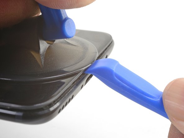
Fessura del pannello dello schermo: Questa fessura fa parte del gruppo dello schermo. Non fare leva in questa fessura, o separerai e danneggerai il pannello dello schermo.
-
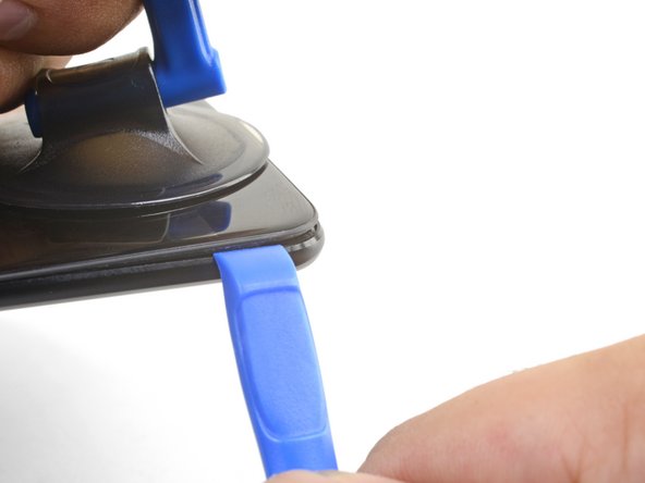
Fessura della cornice: Questa è dove la cornice in plastica incontra la copertura posteriore. Fai leva solo in questa fessura.
-
Ci sono dodici ganci che fissano la cornice contro la copertura posteriore. Ricordati la loro posizione mentre rimuovi la copertura posteriore nei prossimi passaggi.
-
-
-
Dopo aver liberato i bordi inferiore e sinistro del telefono, fai ondeggiare delicatamente la cornice per rilasciare i ganci dei bordi superiore e destro.
-
Allinea il bordo superiore della cornice alla copertura posteriore ed assicurati che i ganci superiori si infilino in posizione.
-
Schiaccia i bordi lunghi del telefono per far scattare i ganci restanti.
-
-
-
-
Usa la punta di uno spudger per sollevare e scollegare il connettore della batteria dalla sua presa.
-
-
-
Svita le sei viti a croce Phillips da 2,6 mm che fissano lo speaker principale alla cornice.
-
-
-
Usa la punta di uno spudger per sollevare e scollegare il cavo a nastro di interconnessione dalla presa.
-
-
Questo passaggio è privo di traduzione. Aiuta a tradurlo
-
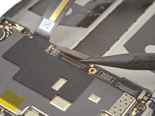
Use the point of a spudger to pry up and disconnect the display interconnect cable from its socket near the bottom edge of the motherboard.
-
-
Questo passaggio è privo di traduzione. Aiuta a tradurlo
-
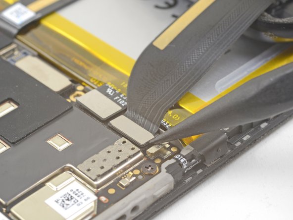
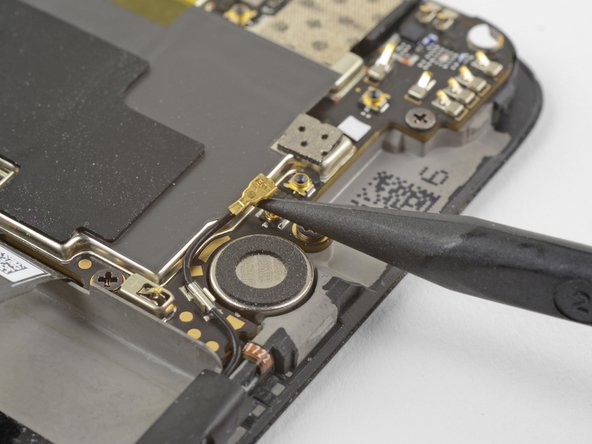
Slide the point of a spudger underneath the antenna interconnect cable that is connected to the motherboard above the vibration motor.
-
Pry up to disconnect the cable from its socket.
-
De-route the cable out of its motherboard grounding clip and move it out of the way.
-
-
Questo passaggio è privo di traduzione. Aiuta a tradurlo
-
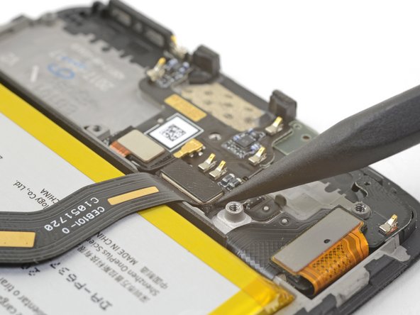
Slide the point of a spudger under the small square antenna connector connected to the motherboard near the top edge.
-
Pry up to disconnect the antenna connector from its socket.
-
-
Questo passaggio è privo di traduzione. Aiuta a tradurlo
-
Remove the following seven 2.6 mm Phillips screws securing the motherboard:
-
-
Questo passaggio è privo di traduzione. Aiuta a tradurlo
-
Use your fingers to lift up the top edge of the motherboard.
-
Lift the motherboard out of its recess and remove it.
-
-
Questo passaggio è privo di traduzione. Aiuta a tradurlo
-
Use tweezers or the point of a spudger to pry up and remove the black tape covering the volume buttons on the right edge of the phone.
-
Repeat the process with the black tape covering the power button on the left edge of the phone.
-
-
Questo passaggio è privo di traduzione. Aiuta a tradurlo
-
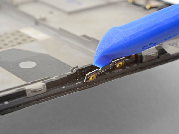
Use the edge of an opening tool to gently pry the volume button board away from the frame.
-
Continue prying until you loosen the volume button board from the frame.
-
-
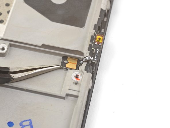
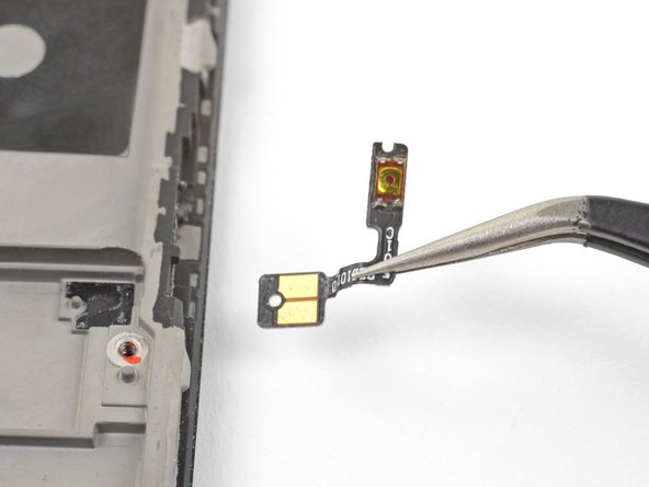
Questo passaggio è privo di traduzione. Aiuta a tradurlo
-
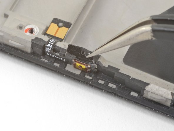
Squeeze the tweezer tips together and insert the point underneath the volume button board's contact pad near the top right edge of the frame.
-
Pry upwards to loosen the contact pad from the frame.
-
Remove the volume buttons.
-
-
Questo passaggio è privo di traduzione. Aiuta a tradurlo
-
Repeat the previous two steps to remove the power button from the left edge of the frame.
-


Annulla: non ho completato questa guida.
Altre 6 persone hanno completato questa guida.


2 Commenti
I’ve just spent the afternoon migrating to a new frame, and the power button seating lugs were just a tiny bit mislocated. The result was permanent press on the power button when the back was fitted. I resolved this by trimming the power button circuit board with some sharp sidecutters. Charging now and seems ok. Would have been much harder without my ifixit toolkit.
Fantastic guide! Thanks! Some steps were slightly different for my OnePlus 5T but still quite helpful! I used it to replace the power button that was barely working.
Unfortunately it seems my replacement part had maybe slightly different tolerances and the button was being pressed permanently. I managed to fix it by very carefully shaving off a little bit of the case's mechanism that presses the button.