Salta al contenuto principale

Questa versione può contenere modifiche errate. Passa all'ultima istantanea verificata.

Cosa ti serve

  1. , Vassoio scheda SIM: passo 1, immagine 1 di 3 , Vassoio scheda SIM: passo 1, immagine 2 di 3 , Vassoio scheda SIM: passo 1, immagine 3 di 3
    • Infila uno strumento o una punta per l'eiezione della scheda SIM, o una graffetta raddrizzata nel piccolo foro sotto il vassoio della scheda SIM, posizionato vicino alle fotocamere posteriori sul bordo del telefono.

    • Premi con decisione per espellere il vassoio.

    • Quando reinfili il vassoio della scheda SIM, assicurati che sia orientato correttamente come mostrato.

  2. , Copertura posteriore: passo 2, immagine 1 di 1
    • Svita le due viti Torx T2 da 2,6 mm accanto alla porta USB-C sul bordo inferiore del telefono.

  3. : passo 3, immagine 1 di 3 : passo 3, immagine 2 di 3 : passo 3, immagine 3 di 3
    • C'è un elevato rischio di danneggiare il pannello dello schermo se questa procedura di apertura non viene eseguita correttamente.

    • I prossimi quattro passi mostrano come separare la copertura posteriore dalla cornice in plastica. Leggi tutti i passaggi prima di provare ad eseguire questa procedura.

    • Ci sono due diverse fessure tra il corpo del telefono e lo schermo:

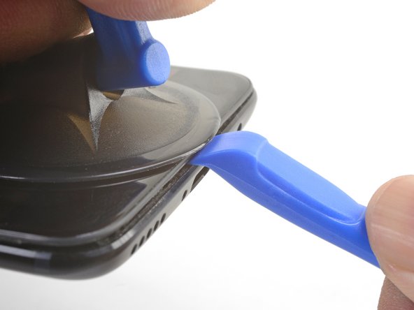
    • Fessura del pannello dello schermo: Questa fessura fa parte del gruppo dello schermo. Non fare leva in questa fessura, o separerai e danneggerai il pannello dello schermo.

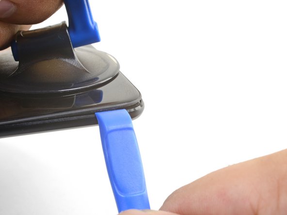
    • Fessura della cornice: Questa è dove la cornice in plastica incontra la copertura posteriore. Fai leva solo in questa fessura.

    • Ci sono dodici ganci che fissano la cornice contro la copertura posteriore. Ricordati la loro posizione mentre rimuovi la copertura posteriore nei prossimi passaggi.

  4. : passo 4, immagine 1 di 2 : passo 4, immagine 2 di 2
    • Mentre procedi, cerca di non accendere accidentalmente il telefono. Se succede, spegnilo prima di procedere.

    • Fai aderire una ventosa vicino al bordo inferiore dello schermo.

    • Tira la ventosa con forza costante.

    • Premi il bordo di uno strumento di apertura nella fessura della cornice vicino alla ventosa finché non si infila tra la cornice in plastica e il bordo della copertura posteriore.

    • A causa degli spazi ristretti, questo richiederà parecchia forza. Usare un nuovo strumento di apertura con un bordo intatto ti aiuterà in questo passaggio.

  5. : passo 5, immagine 1 di 3 : passo 5, immagine 2 di 3 : passo 5, immagine 3 di 3
    • Dopo aver infilato lo strumento di apertura, fallo scorrere attentamente sotto il bordo inferiore del telefono.

    • Guida attentamente lo strumento di apertura attorno all'angolo in basso a sinistra del telefono mentre lo tieni infilato nella fessura.

  6. : passo 6, immagine 1 di 2 : passo 6, immagine 2 di 2
    • Fai leva con lo strumento di apertura per rilasciare il primo gancio dalla cornice.

  7. : passo 7, immagine 1 di 3 : passo 7, immagine 2 di 3 : passo 7, immagine 3 di 3
    • Continua a far scorrere lo strumento di apertura sotto il bordo lungo, rilasciando i ganci sulla strada.

    • L'ultimo gancio nell'angolo in alto a sinistra, vicino al selettore di modalità, è incassato e può essere difficile da rilasciare. Prenditi tutto il tempo necessario ed usa la parte piatta di uno spudger o un plettro per aiutarti.

  8. : passo 8, immagine 1 di 1
    • Dopo aver liberato i bordi inferiore e sinistro del telefono, fai ondeggiare delicatamente la cornice per rilasciare i ganci dei bordi superiore e destro.

    • La cornice è ancora collegata alla copertura posteriore tramite un lungo cavo a nastro. Non rimuovere la copertura posteriore.

    • Durante il rimontaggio, fermati qui per provare la funzionalità del tuo telefono prima di richiudere la copertura posteriore.

    • Per richiudere la copertura posteriore:

    • Allinea il bordo superiore della cornice alla copertura posteriore ed assicurati che i ganci superiori si infilino in posizione.

    • Schiaccia i bordi lunghi del telefono per far scattare i ganci restanti.

  9. : passo 9, immagine 1 di 3 : passo 9, immagine 2 di 3 : passo 9, immagine 3 di 3
    • Dopo aver rilasciato tutti i ganci, gira il telefono in modo che lo schermo sia rivolto verso il basso.

    • Ruota la copertura ed appoggiala sulla cornice esposta.

    • Stai attento a non tirare il cavo a nastro che collega la copertura posteriore alla cornice.

  10. : passo 10, immagine 1 di 2 : passo 10, immagine 2 di 2
    • Svita la vite a croce Phillips da 2,6 mm che tiene ferma la copertura del cavo sopra la batteria.

    • Solleva e rimuovi la copertura del cavo.

    • Per reinstallare la copertura, posiziona correttamente un'estremità e piega leggermente la copertura per posizionare l'altra estremità.

  11. : passo 11, immagine 1 di 2 : passo 11, immagine 2 di 2
    • Usa la punta di uno spudger per sollevare e scollegare il cavo a nastro della copertura posteriore dalla sua presa.

    • Per ricollegare i connettori a pressione come questo, allinea attentamente e premi su un lato, quindi ripeti per l'altro lato. Non premere nel centro. Se il connettore non è allineato correttamente, i contatti si possono piegare, causando danni permanenti.

  12. : passo 12, immagine 1 di 1
    • Rimuovi la copertura posteriore.

  13. , Scollegamento batteria OnePlus 5: passo 13, immagine 1 di 2 , Scollegamento batteria OnePlus 5: passo 13, immagine 2 di 2
    • Usa la punta di uno spudger per sollevare e scollegare il connettore della batteria dalla sua presa.

  14. , Speaker principale: passo 14, immagine 1 di 1
    • Svita le sei viti a croce Phillips da 2,6 mm che fissano lo speaker principale alla cornice.

  15. : passo 15, immagine 1 di 2 : passo 15, immagine 2 di 2
    • Infila la parte piatta di uno spudger nell'angolo del gruppo dello speaker principale e sollevalo leggermente, rilasciando lo speaker principale dal suo alloggio.

  16. : passo 16, immagine 1 di 1
    • Rimuovi lo speaker principale.

    • Per reinstallare lo speaker principale, allineane il bordo inferiore alla cornice, quindi premilo in posizione.

    • Durante il rimontaggio, assicurati che il connettore del cavo dello schermo sotto il gruppo dello speaker principale sia ancora collegato saldamente.

  17. , Scollegamento cavo di interconnessione OnePlus 5: passo 17, immagine 1 di 3 , Scollegamento cavo di interconnessione OnePlus 5: passo 17, immagine 2 di 3 , Scollegamento cavo di interconnessione OnePlus 5: passo 17, immagine 3 di 3
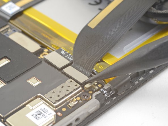
    • Usa la punta di uno spudger per sollevare e scollegare il cavo a nastro di interconnessione dalla presa.

    • Se stai sostituendo la batteria, piega il cavo a nastro di interconnessione lontano dal telefono e fissalo con un elastico o del nastro.

  18. , Batteria: passo 18, immagine 1 di 1
    • Solleva l'aletta di tiraggio verde dalla batteria.

  19. : passo 19, immagine 1 di 3 : passo 19, immagine 2 di 3 : passo 19, immagine 3 di 3
    • Tieni ferma la cornice del telefono contro il tavolo.

    • Facendo forza costante, tira l'aletta di tiraggio verde verso l'alto finché la batteria non si libera dal suo alloggio.

    • Se stai avendo delle difficoltà, applica dell'alcool isopropilico ad alta concentrazione (> 90%) lungo la fessura della batteria per ammorbidire l'adesivo.

    • Ruota completamente la batteria fuori dal suo alloggio e rimuovila dal rivestimento in plastica.

  20. : passo 20, immagine 1 di 1
    • Rimuovi la batteria.

    • Non riutilizzare la batteria dopo averla rimossa. Riutilizzare una batteria piegata o danneggiata è un potenziale rischio per la sicurezza.

    • Se la batteria sostitutiva non ha una linguetta di estrazione, puoi prenderla dalla vecchia batteria e applicarla a quella nuova, per facilitare future ed eventuali sostituzioni.

    • Mentre installi la batteria, connetti temporaneamente la batteria al telefono per assicurare un corretto allineamento.

    • Se stai installando una batteria su un nuovo modulo schermo + digitizer, assicurati di staccare il rivestimento adesivo blu scuro per esporre l'adesivo per la nuova batteria.

  21. Questo passaggio è privo di traduzione. Aiuta a tradurlo

    : passo 21, immagine 1 di 2 : passo 21, immagine 2 di 2
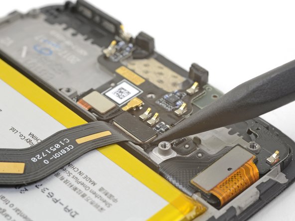
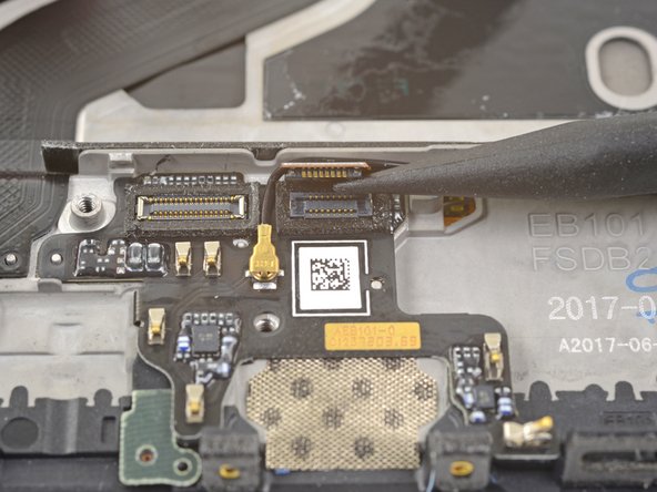
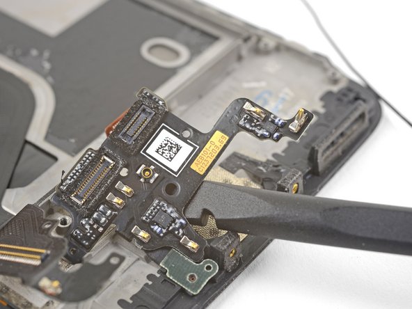
    • Use the point of a spudger the pry up and disconnect the fingerprint scanner connector from its socket on the daughterboard.

  22. Questo passaggio è privo di traduzione. Aiuta a tradurlo

    : passo 22, immagine 1 di 3 : passo 22, immagine 2 di 3 : passo 22, immagine 3 di 3
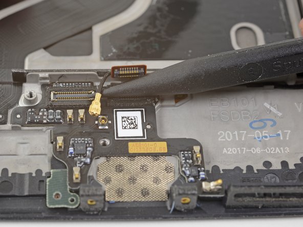
    • Slip the point of a spudger underneath the antenna interconnect cable and pry up to disconnect it from its socket on the daughterboard.

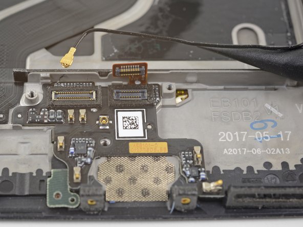
    • De-route the antenna interconnect cable out of the way of the daughterboard.

  23. Questo passaggio è privo di traduzione. Aiuta a tradurlo

    : passo 23, immagine 1 di 2 : passo 23, immagine 2 di 2
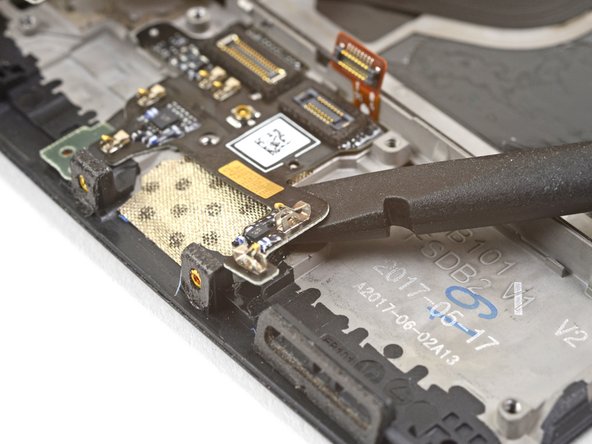
    • Insert the edge of a flat end of the spudger underneath the microphone board and twist slightly to release the board's adhesive.

  24. Questo passaggio è privo di traduzione. Aiuta a tradurlo

    : passo 24, immagine 1 di 3 : passo 24, immagine 2 di 3 : passo 24, immagine 3 di 3
    • Slide the flat end of a spudger or the point of an opening pick underneath the daughterboard near its right edge.

    • Gently pry to loosen the daughterboard from its recess.

    • If the daughterboard begins to bend significantly, stop and pry from a different angle.

  25. Questo passaggio è privo di traduzione. Aiuta a tradurlo

    : passo 25, immagine 1 di 3 : passo 25, immagine 2 di 3 : passo 25, immagine 3 di 3
    • Insert the flat end of a spudger underneath the daughterboard, this time approaching it from the bottom.

    • Twist and slide the spudger slightly to release the daughterboard from its recess.

  26. Questo passaggio è privo di traduzione. Aiuta a tradurlo

    : passo 26, immagine 1 di 1
  27. Questo passaggio è privo di traduzione. Aiuta a tradurlo

    : passo 27, immagine 1 di 2 : passo 27, immagine 2 di 2
    Attrezzo utilizzato in questo passaggio:
    Electrical Tape in 6 Assorted Colors
    $7.99
    Compra
    • Slide the flat end of a spudger underneath the tape covering the fingerprint scanner.

    • Lift up to pry and remove the tape.

    • You will most likely not be able to reuse the tape during reinstallation. Replace it with a piece of electrical tape.

  28. Questo passaggio è privo di traduzione. Aiuta a tradurlo

    : passo 28, immagine 1 di 2 : passo 28, immagine 2 di 2
    • If you are planning to reuse the fingerprint scanner, be extremely careful pulling the flex cable up. It is very delicate and prone to breaking.

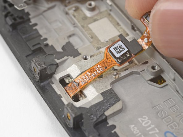
    • Use your finger to gently lift up the connector end of the fingerprint scanner. Pull upwards slowly. Do not pull directly away from the fingerprint scanner.

    • Keep pulling upwards until the fingerprint scanner cable is freed from its recess.

  29. Questo passaggio è privo di traduzione. Aiuta a tradurlo

    : passo 29, immagine 1 di 3 : passo 29, immagine 2 di 3 : passo 29, immagine 3 di 3
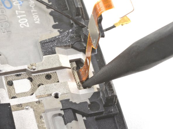
    • Insert the point of a spudger into the marked areas on either side of the flex cable, and push until the fingerprint scanner is loosened from its recess.

    • Do not apply pressure directly onto the delicate flex cable.

    • If the fingerprint scanner is not coming loose, make sure you are pressing the spudger's point against the backside of the scanner as indicated in the first image, and not the metal plate below it.

  30. Questo passaggio è privo di traduzione. Aiuta a tradurlo

    : passo 30, immagine 1 di 2 : passo 30, immagine 2 di 2
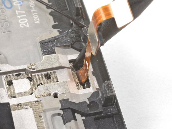
    • Once the fingerprint scanner is loosened from its recess, carefully thread its flex cable through the cutout, out of the front of the display.

    • Remove the fingerprint scanner.

    • If you are installing the fingerprint scanner onto a replacement frame, be sure to peel off the blue adhesive liner for the fingerprint scanner before sticking it in place.

  31. Questo passaggio è privo di traduzione. Aiuta a tradurlo

    : passo 31, immagine 1 di 2 : passo 31, immagine 2 di 2
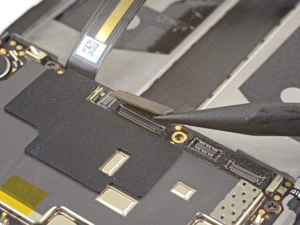
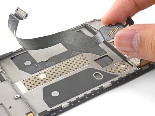
    • Use the point of a spudger to pry up and disconnect the display interconnect cable from its socket near the bottom edge of the motherboard.

  32. Questo passaggio è privo di traduzione. Aiuta a tradurlo

    : passo 32, immagine 1 di 2 : passo 32, immagine 2 di 2
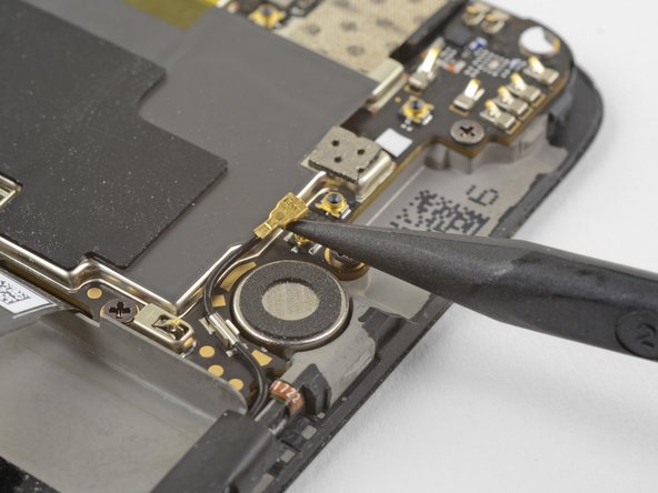
    • Slide the point of a spudger underneath the antenna interconnect cable that is connected to the motherboard above the vibration motor.

    • Pry up to disconnect the cable from its socket.

    • De-route the cable out of its motherboard grounding clip and move it out of the way.

  33. Questo passaggio è privo di traduzione. Aiuta a tradurlo

    : passo 33, immagine 1 di 2 : passo 33, immagine 2 di 2
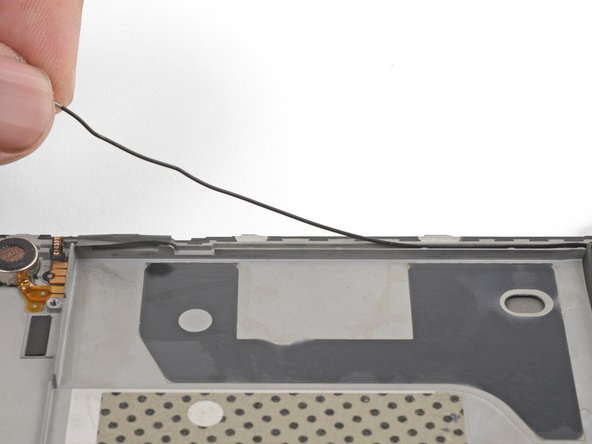
    • Slide the point of a spudger under the small square antenna connector connected to the motherboard near the top edge.

    • Pry up to disconnect the antenna connector from its socket.

  34. Questo passaggio è privo di traduzione. Aiuta a tradurlo

    : passo 34, immagine 1 di 1
    • Remove the following seven 2.6 mm Phillips screws securing the motherboard:

    • Some screws may be hidden under stickers. Remove the stickers to access the screws.

  35. Questo passaggio è privo di traduzione. Aiuta a tradurlo

    : passo 35, immagine 1 di 3 : passo 35, immagine 2 di 3 : passo 35, immagine 3 di 3
    • Use your fingers to lift up the top edge of the motherboard.

    • Lift the motherboard out of its recess and remove it.

  36. Questo passaggio è privo di traduzione. Aiuta a tradurlo

    : passo 36, immagine 1 di 2 : passo 36, immagine 2 di 2
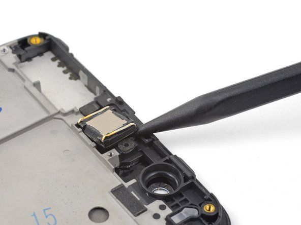
    • Insert the point of a spudger under the top right corner of the earpiece module and pry up, loosening the module from its recess.

  37. Questo passaggio è privo di traduzione. Aiuta a tradurlo

    : passo 37, immagine 1 di 1
    • Remove the earpiece module.

    • During reinstallation, be sure that the earpiece module is properly oriented such that the gold contacts face downwards.

    • If you are transferring the earpiece module to a replacement frame, be sure to peel and remove the white adhesive liner before pressing the earpiece module into place.

  38. Questo passaggio è privo di traduzione. Aiuta a tradurlo

    : passo 38, immagine 1 di 3 : passo 38, immagine 2 di 3 : passo 38, immagine 3 di 3
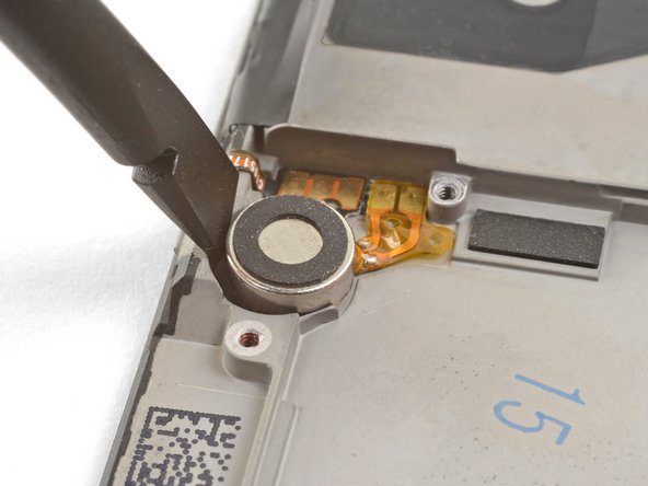
    • Wedge the point of an opening pick between the vibration motor and the frame and push downward to loosen the vibration motor from its recess.

    • Once the vibration motor is slightly loosened, you can wedge the flat end of a spudger between the motor and the frame to help free it from its recess.

  39. Questo passaggio è privo di traduzione. Aiuta a tradurlo

    : passo 39, immagine 1 di 2 : passo 39, immagine 2 di 2
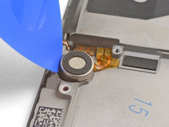
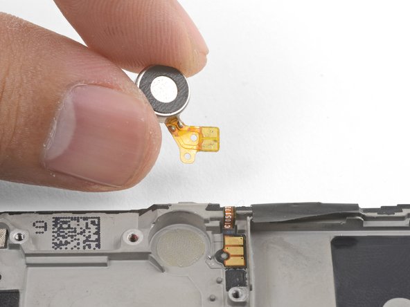
    • Slide the point of an opening pick underneath the vibration motor's flex pad and gently pry it off of the frame.

    • Remove the vibration motor.

  40. Questo passaggio è privo di traduzione. Aiuta a tradurlo

    : passo 40, immagine 1 di 2 : passo 40, immagine 2 di 2
    Attrezzo utilizzato in questo passaggio:
    Electrical Tape in 6 Assorted Colors
    $7.99
    Compra
    • Try not to tear the black tape pieces in this step so that you can reuse them during re-assembly. If you do tear the tape, replace them with pieces of electrical tape.

    • Use tweezers or the point of a spudger to pry up and remove the black tape covering the volume buttons on the right edge of the phone.

    • Repeat the process with the black tape covering the power button on the left edge of the phone.

  41. Questo passaggio è privo di traduzione. Aiuta a tradurlo

    : passo 41, immagine 1 di 3 : passo 41, immagine 2 di 3 : passo 41, immagine 3 di 3
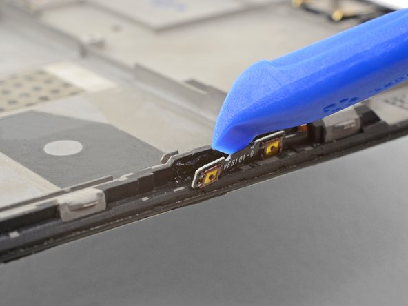
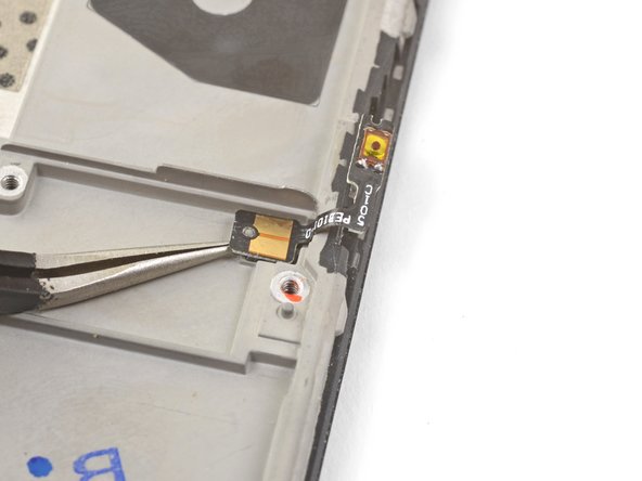
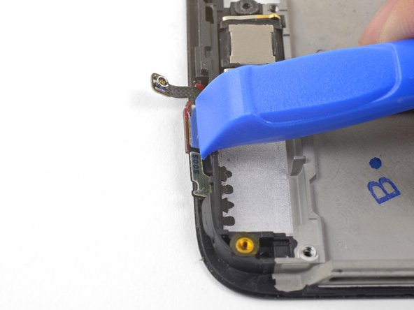
    • Use the edge of an opening tool to gently pry the volume button board away from the frame.

    • If the volume button board begins to bend significantly, stop and pry from a different angle.

    • Continue prying until you loosen the volume button board from the frame.

  42. Questo passaggio è privo di traduzione. Aiuta a tradurlo

    : passo 42, immagine 1 di 3 : passo 42, immagine 2 di 3 : passo 42, immagine 3 di 3
    Attrezzo utilizzato in questo passaggio:
    Tesa 61395 Tape
    $5.99
    Compra
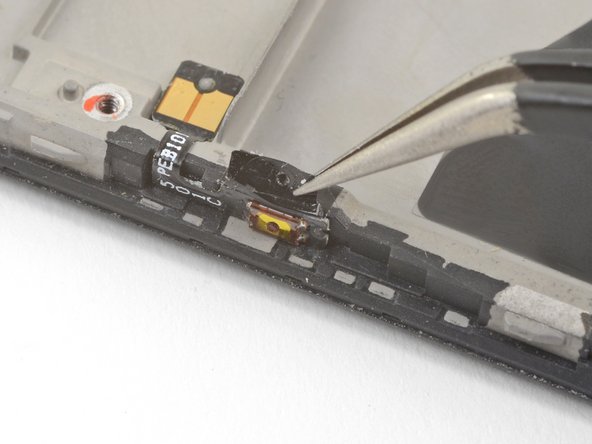
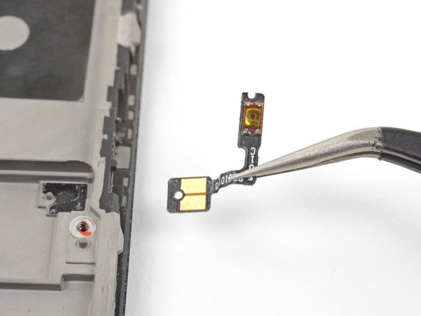
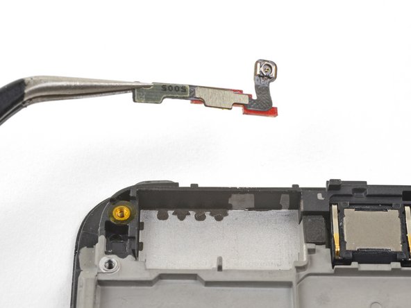
    • Squeeze the tweezer tips together and insert the point underneath the volume button board's contact pad near the top right edge of the frame.

    • Pry upwards to loosen the contact pad from the frame.

    • Remove the volume buttons.

    • To install the volume button board onto a used frame, cut a small piece of adhesive from the pre-cut adhesive card or a roll of Tesa tape, and use it to stick the volume button board back onto the frame.

    • To install the volume button board onto a new replacement frame, peel the blue liner on the right edge of the frame to expose the adhesive. Then, stick the board onto the edge of the frame.

  43. Questo passaggio è privo di traduzione. Aiuta a tradurlo

    : passo 43, immagine 1 di 3 : passo 43, immagine 2 di 3 : passo 43, immagine 3 di 3
    • Repeat the previous two steps to remove the power button from the left edge of the frame.

    • If you are transferring the power button onto a replacement frame, peel the blue liner on the left edge of the frame to expose the adhesive. Then, stick the button onto the edge of the frame.

  44. Questo passaggio è privo di traduzione. Aiuta a tradurlo

    : passo 44, immagine 1 di 1
    • Peel and remove the plastic battery liner from the frame.

    • If your replacement battery did not come with this plastic liner, save it and transfer it to the replacement frame.

  45. Questo passaggio è privo di traduzione. Aiuta a tradurlo

    : passo 45, immagine 1 di 2 : passo 45, immagine 2 di 2
    • Use the point of a spudger to pry up the display connector from its socket near the bottom left corner of the frame.

  46. Questo passaggio è privo di traduzione. Aiuta a tradurlo

    : passo 46, immagine 1 di 3 : passo 46, immagine 2 di 3 : passo 46, immagine 3 di 3
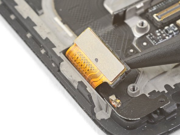
    • Insert the flat end of a spudger underneath the display interconnect cable socket, near where it connected with the display connector in the bottom left corner of the frame.

    • Pry upwards and slide the spudger underneath the cable to loosen the cable from the frame.

  47. Questo passaggio è privo di traduzione. Aiuta a tradurlo

    : passo 47, immagine 1 di 3 : passo 47, immagine 2 di 3 : passo 47, immagine 3 di 3
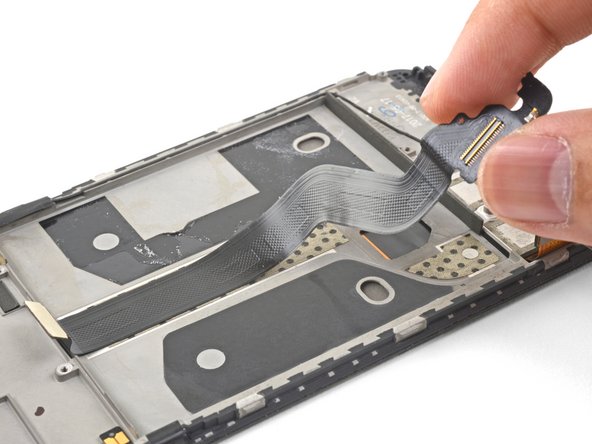
    • Grasp the loosened end of the display interconnect cable with your fingers and pull upwards, releasing the cable from the frame.

    • Remove the display interconnect cable.

    • If you are transferring this onto a replacement frame, peel and remove the blue adhesive liners before sticking the cable in place.

  48. Questo passaggio è privo di traduzione. Aiuta a tradurlo

    : passo 48, immagine 1 di 2 : passo 48, immagine 2 di 2
    • Use your fingers to lift and de-route the antenna interconnect cable from its groove on the right edge of the frame.

    • Transfer the antenna interconnect cable to the new frame.

  49. Questo passaggio è privo di traduzione. Aiuta a tradurlo

    : passo 49, immagine 1 di 3 : passo 49, immagine 2 di 3 : passo 49, immagine 3 di 3
    • Use the edge of an opening tool to push the back cover antenna connector away from the frame. It is located on the top edge of the frame.

    • Remove the back cover antenna connector.

    • If you are transferring the connector onto a replacement frame, peel the blue liner on the top edge of the replacement frame before sticking the connector onto the edge.

  50. Questo passaggio è privo di traduzione. Aiuta a tradurlo

    : passo 50, immagine 1 di 1
    • The bare screen and digitizer assembly remains.

    • Transfer all of the parts you removed in the previous steps from the old assembly to the new one.

Linea Traguardo

Altre 32 persone hanno completato questa guida.

Arthur Shi

Membro da: 01/03/18

254.032 Reputazione

529 Guide realizzate

Team

iFixit Membro di iFixit

Staff

135 Membri

17.243 Guide realizzate

17 Commenti

Nice. But where do you get the replacement part from?

Christos Mantas - Replica

Dear Christos, hope it is not too late, you can check Oneplus 5 screen replacement from Witrigs

Witrigs - Replica

HI . Do I need to buy an original screen and digitizer for my oneplus 5?

I'm from Argentina and on EBAY I do not see ORIGINAL parts

Can someone help me?

Joselo - Replica

Hi Joselo,

You do not need an original, but that is probably the best quality. The original screen is AMOLED. There are also OLED and LCD replacement screens. These will not be as bright as the original AMOLED panel.

Arthur Shi -

Hi, I need to know if this screen is like the original (Amoled) or not, and approximately how long it takes to send by mail to Miami Florida. Thank you OnePlus 5 Screen

Joselo - Replica

Aggiungi Commento

Visualizza Statistiche:

Ultime 24 Ore: 4

Ultimi 7 Giorni: 28

Ultimi 30 Giorni: 198

Tutti i Tempi: 36,048