Questa versione può contenere modifiche errate. Passa all'ultima istantanea verificata.
Cosa ti serve
-
-
Svita le due viti a croce Philips che fissano il copribatteria al case inferiore.
-
Prendi il copribatteria e sollevalo dal case inferiore.
-
-
-
Usando uno spudger (o un'unghia), solleva la batteria dalla parte superiore.
-
Prendi la batteria e rimuovila dal DSi.
-
-
-
Ci sono due viti nascoste sotto i due gommini cerchiati in rosso.
-
Usa la punta dello spudger per estrarre i due gommini dal case inferiore.
-
-
-
Inserisci lo spudger tra il case inferiore e il pannello inferiore vicino all'angolo in alto a destra del DSi.
-
Passa delicatamente lo spudger lungo il margine del case esterno, creando uno spazio tra il case e il dispositivo.
-
Continua a passare lo spudger intorno al dispositivo fino a separare il case inferiore quasi del tutto.
-
-
Questo passaggio è privo di traduzione. Aiuta a tradurlo
-
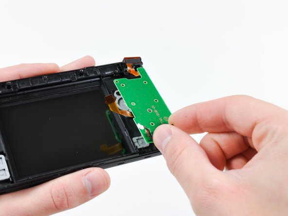
Pull the Wi-Fi board away from the motherboard by its edge closest to the headphone jack.
-
-
Questo passaggio è privo di traduzione. Aiuta a tradurlo
-
Pry the Wi-Fi antenna connector straight up from its socket on the Wi-Fi board.
-
-
Questo passaggio è privo di traduzione. Aiuta a tradurlo
-
Use the tip of a spudger to pry the power board connector out of its socket on the motherboard.
-
-
Questo passaggio è privo di traduzione. Aiuta a tradurlo
-
Use your fingernail or the edge of a plastic opening tool to flip up the retaining flap on the following three ZIF sockets:
-
Lower touchscreen cable
-
Lower LCD cable
-
Power board cable
-
After flipping up the locking tabs on all three sockets, use your fingers or a pair of tweezers to gently pull the cables straight out of their sockets.
-
-
Questo passaggio è privo di traduzione. Aiuta a tradurlo
-
Use your fingernail or the edge of a plastic opening tool to carefully flip up the touchscreen ribbon cable retaining flap.
-
Use the tip of a spudger to pull the touchscreen ribbon cable straight out of its socket.
-
-
-
Questo passaggio è privo di traduzione. Aiuta a tradurlo
-
Use your fingernail or the edge of a plastic opening tool to carefully flip up the dual camera ribbon cable retaining flap.
-
Use the tip of a spudger to pull the dual camera ribbon cable straight out of its socket.
-
-
Questo passaggio è privo di traduzione. Aiuta a tradurlo
-
With the tip of a spudger, Pry the microphone antenna up off its socket on the motherboard.
-
-
Questo passaggio è privo di traduzione. Aiuta a tradurlo
-
Remove the following four Phillips screws securing the motherboard to the DSi framework.
-
Three longer screws.
-
One short screw.
-
Pull the microphone and Wi-Fi antenna cables out of the notch cut into the motherboard near the headphone jack.
-
-
Questo passaggio è privo di traduzione. Aiuta a tradurlo
-
Slightly lift the motherboard upwards to reveal the upper LCD ribbon cable above the ABXY buttons .
-
Use your fingernail or the edge of a plastic opening tool to carefully flip up the upper LCD ribbon cable retaining flap.
-
Remove the motherboard from the DSi.
-
-
Questo passaggio è privo di traduzione. Aiuta a tradurlo
-
Use the tip of a spudger to pry the metal backing of the lower LCD up from the DSi's framework.
-
Lift the lower LCD assembly out of the DSi.
-
-
Questo passaggio è privo di traduzione. Aiuta a tradurlo
-
Use a pushpin to remove the four plastic screw covers on the front bezel.
-
-
Questo passaggio è privo di traduzione. Aiuta a tradurlo
-
Remove the four Phillips screws securing the rear bezel to the front bezel.
-
-
Questo passaggio è privo di traduzione. Aiuta a tradurlo
-
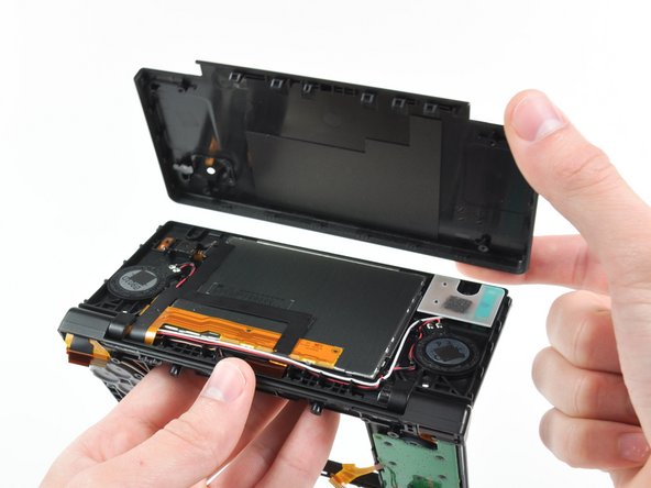
Using two hands, gently slide the rear bezel upwards.
-
Slightly close the case of the DSi and lift the rear bezel straight up out of the DSi.
-
-
Questo passaggio è privo di traduzione. Aiuta a tradurlo
-
Continue de-routing the microphone and Wi-Fi antenna cables through the opening located on the bottom DSi's framework.
-
-
Questo passaggio è privo di traduzione. Aiuta a tradurlo
-
Remove the five Phillips screws securing the power board to the DSi's framework.
-
Lift and remove the power board from the DSi.
-
-
Questo passaggio è privo di traduzione. Aiuta a tradurlo
-
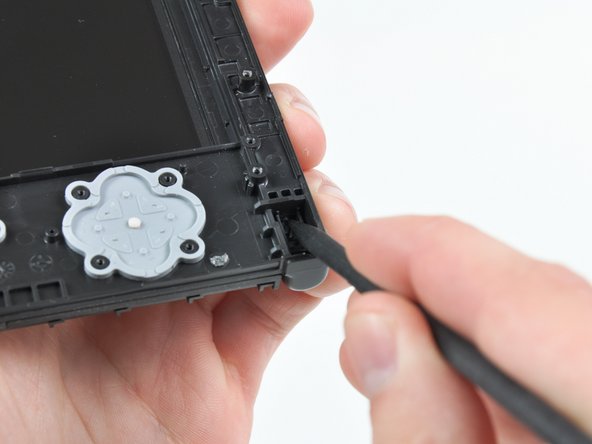
Push the metal hinge pin inward on the D-pad side of the front lower panel with the tip of a spudger.
-
The pin should move about 3 mm and stop. It is not necessary to try to completely remove the pin.
-
-
Questo passaggio è privo di traduzione. Aiuta a tradurlo
-
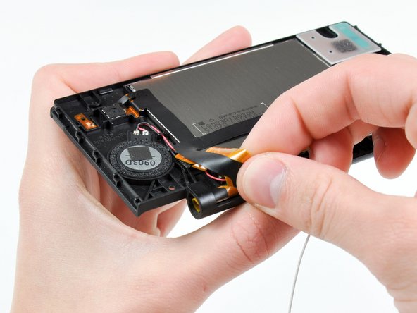
Slightly detach the lower and upper halves of the DSi.
-
De-route the upper LCD and dual camera ribbon cables through the slit near the ABXY side of the front lower panel.
-
Separate the lower and upper halves from each other.
-
-
Questo passaggio è privo di traduzione. Aiuta a tradurlo
-
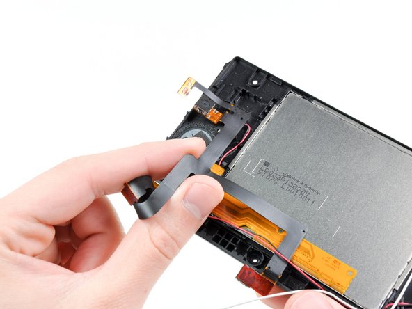
Using your fingers, grasp the microphone cable and de-route it through the hinge.
-
The microphone will likely pop out of its housing, so it is probably easier to completely remove it at this point.
-
De-route the Wi-Fi cable through the hinge.
-
-
Questo passaggio è privo di traduzione. Aiuta a tradurlo
-
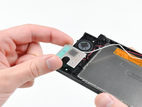
Tightly coil the display and dual camera ribbon cables enough to push them through the steel hinge tube.
-
Remove the steel hinge tube.
-
Carefully push both coiled ribbon cables through the tube molded into the front upper panel.
-
-
Questo passaggio è privo di traduzione. Aiuta a tradurlo
-
Pry the front-facing camera straight up out of its housing in the front bezel.
-
-
Questo passaggio è privo di traduzione. Aiuta a tradurlo
-
Lift the rear-facing camera out of its housing in the front bezel.
-
Remove the dual camera cable assembly from the DSi.
-
-
Questo passaggio è privo di traduzione. Aiuta a tradurlo
-
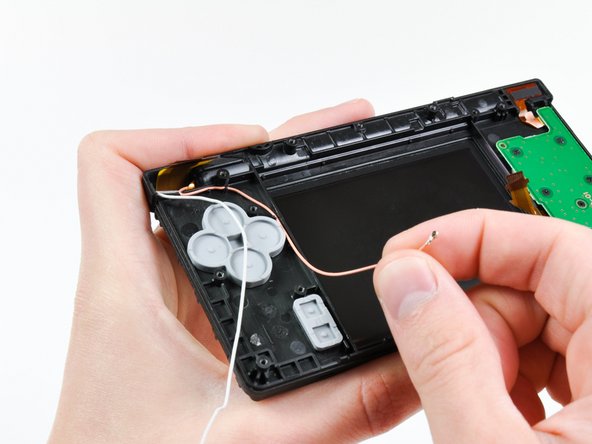
De-route the Wi-Fi antenna cable from its channel in the front bezel.
-
Lift the Wi-Fi antenna board straight up and remove it from the DSi.
-
-
Questo passaggio è privo di traduzione. Aiuta a tradurlo
-
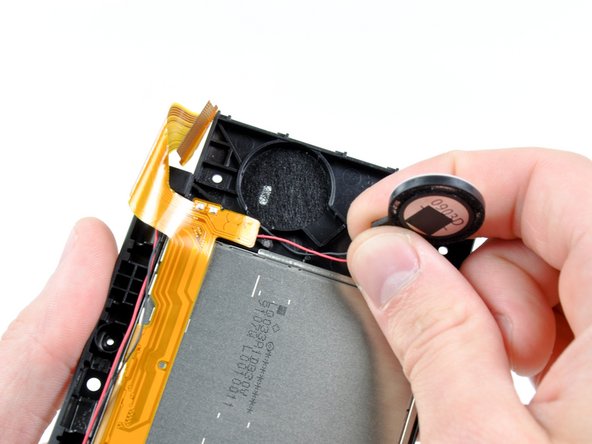
Use the flat end of a spudger to pry the right speaker straight up and out of its housing in the front upper panel.
-
Lift the right speaker and set it on top of the upper LCD.
-
-
Questo passaggio è privo di traduzione. Aiuta a tradurlo
-
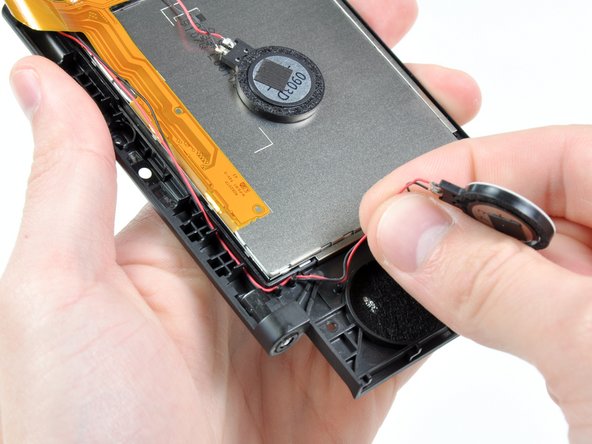
In the same manner as previously described, remove the left speaker.
-
De-route the left speaker cables from underneath the upper LCD.
-
Lay the left speaker on top of the upper LCD.
-
-
Questo passaggio è privo di traduzione. Aiuta a tradurlo
-
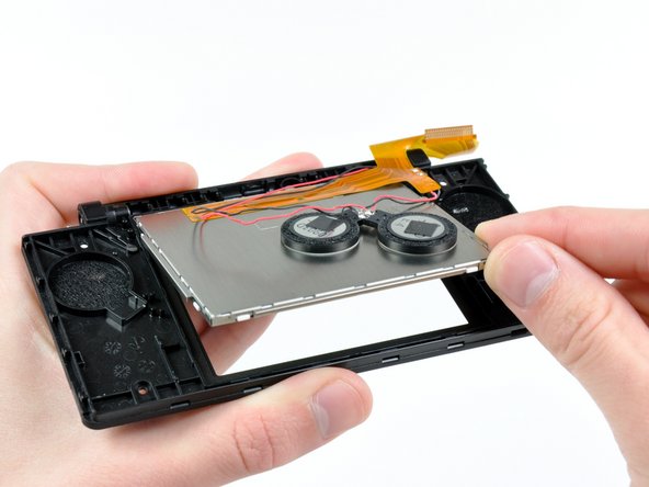
Cautiously wedge the flat end of spudger underneath the upper LCD.
-
Loosen the adhesive by running the spudger along the perimeter of the upper LCD.
-
Lift the upper LCD by its upper right corner and remove it from the front upper panel.
-
-
Questo passaggio è privo di traduzione. Aiuta a tradurlo
-
Desolder the speakers from the upper LCD by heating up the solder joints with a soldering iron and simultaneously using a pair of tweezers to pull the speaker wires away from the logic board.
-


Annulla: non ho completato questa guida.
Altre 30 persone hanno completato questa guida.

12 Commenti
The tricky part is getting the upper screen and black ribbon through the hinge. I found that curling them and pushing them through a drinking straw that was cut short first and then pushing the straw through the hinge hole made it a whole lot easier.
So true. I just broke my second ribbon cable while replacing the case. While most repairs on the dsi are relatively easy, this ribbon cable makes any repairs that involve it a nightmare.
I curled the larger (new) cable the same way the smaller one was already curled. Just spend some time doing that until it was shaped that way and it was a lot easier to get both through the molded tube and ring.
Tplan -
While doing this I accident messed something up. When I power on the DSi, the bottom screen just flashes and the DS turns off. What did I do wrong?