Salta al contenuto principale

Questa versione può contenere modifiche errate. Passa all'ultima istantanea verificata.

Cosa ti serve

  1. Questo passaggio è privo di traduzione. Aiuta a tradurlo

    : passo 1, immagine 1 di 2 : passo 1, immagine 2 di 2
    • Insert the point of the SIM card eject tool into the sim card lock at the top of the phone.

    • Press down on the SIM card eject tool until the SIM card tray is slightly ejected from the device.

  2. Questo passaggio è privo di traduzione. Aiuta a tradurlo

    : passo 2, immagine 1 di 2 : passo 2, immagine 2 di 2
    • Remove the SIM card tray from the phone.

  3. , Schermo: passo 3, immagine 1 di 2 , Schermo: passo 3, immagine 2 di 2
    • Usando l'estremità piatta dello spudger in nylon, tira via il nastro adesivo nero disposto sopra il connettore dello schermo a cui è attaccato il nastro nero.

  4. : passo 4, immagine 1 di 3 : passo 4, immagine 2 di 3 : passo 4, immagine 3 di 3
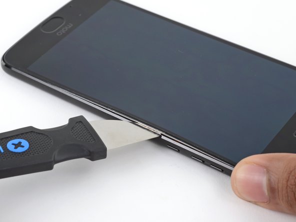
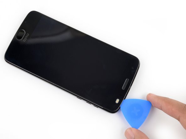
    • Incunea lo strumento di apertura in plastica nella fessura creata dalla separazione tra schermo e scocca nell'angolo inferiore destro per tenerlo aperto.

    • Inserisci lo spudger in nylon nell'angolo inferiore sinistro dello schermo e fai leva per sollevare il display.

    • Continua a inserire gli strumenti di apertura in plastica e lo spudger tutto attorno al telefono e fai leva sullo schermo nei vari punti finché non si separa completamente dal dispositivo.

    • Rimuovi lo schermo con delicatezza e lentezza, altrimenti il display potrebbe rompersi.

  5. Questo passaggio è privo di traduzione. Aiuta a tradurlo

    : passo 5, immagine 1 di 2 : passo 5, immagine 2 di 2
    • With the Jimmy still inserted, insert an opening pick under the silver midframe, on top of the Jimmy in the same location

    • Remove the Jimmy.

  6. : passo 6, immagine 1 di 3 : passo 6, immagine 2 di 3 : passo 6, immagine 3 di 3
    • Inserisci lo spudger al di sotto del blocco del sistema di ritenuta che collega il nastro nero dello schermo alla scocca.

    • Spingi in alto il blocco per liberare la ritenuta.

    • Separa il nastro nero dalla ritenuta tirandolo delicatamente verso sinistra.

  7. : passo 7, immagine 1 di 3 : passo 7, immagine 2 di 3 : passo 7, immagine 3 di 3
    • Rimuovi lo schermo alzandolo da destra e facendo perno sul bordo sinistro; disponi lo schermo a faccia in giù a fianco della scocca del dispositivo.

  8. Questo passaggio è privo di traduzione. Aiuta a tradurlo

    : passo 8, immagine 1 di 2 : passo 8, immagine 2 di 2
    • When separating the left side of the screen assembly, take care to not snag the display cable located on the left edge near the bottom of the display.

  9. Questo passaggio è privo di traduzione. Aiuta a tradurlo

    : passo 9, immagine 1 di 3 : passo 9, immagine 2 di 3 : passo 9, immagine 3 di 3
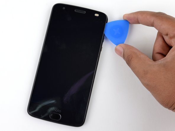
    • Insert another opening pick underneath the bottom edge of the screen assembly and slide it around the bottom left corner of the device so it is underneath the assembly's left edge.

    • Slide your tool all along the left edge of the phone to separate the metal clips and adhesive securing the screen assembly.

    • Like before, ensure you are separating the entire assembly by identifying the three metal clips on the right edge of the device.

  10. Questo passaggio è privo di traduzione. Aiuta a tradurlo

    : passo 10, immagine 1 di 3 : passo 10, immagine 2 di 3 : passo 10, immagine 3 di 3
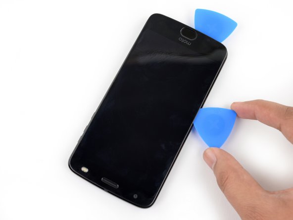
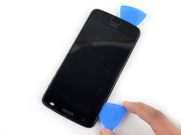
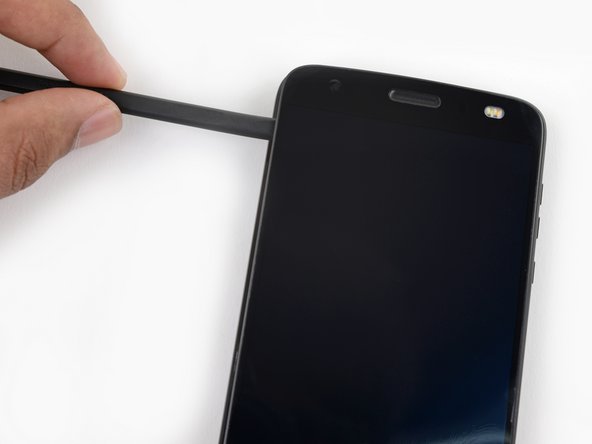
    • Slide your tool around the top edge of the screen assembly and slice all along it to slice through its adhesive.

    • Take care to not insert your tool more than ~4 mm past the edge of the display to prevent damaging the front facing sensor array.

  11. Questo passaggio è privo di traduzione. Aiuta a tradurlo

    : passo 11, immagine 1 di 2 : passo 11, immagine 2 di 2
    • There are two large pads of adhesive securing the screen assembly near the top edge but further past the 4 mm that have already been sliced through.

    • The front facing sensor array and cable surround the right patch of adhesive from the top and right, so prying or slicing from the top or right edge may damage the cable. The following steps will describe how to separate the adhesive from the left edge.

  12. Questo passaggio è privo di traduzione. Aiuta a tradurlo

    : passo 12, immagine 1 di 1
    • Apply a small amount of high concentration (>90%) isopropyl alcohol underneath the screen assembly's left edge, near the top of the device.

    • Allow the device to sit upright on its right edge for ~5 minutes to allow the alcohol to penetrate and weaken the adhesive.

  13. Questo passaggio è privo di traduzione. Aiuta a tradurlo

    : passo 13, immagine 1 di 3 : passo 13, immagine 2 di 3 : passo 13, immagine 3 di 3
    • Insert an opening pick as deep as possible under the top left corner of the screen assembly to slice through the left patch of adhesive.

  14. Questo passaggio è privo di traduzione. Aiuta a tradurlo

    : passo 14, immagine 1 di 3 : passo 14, immagine 2 di 3 : passo 14, immagine 3 di 3
    • Slowly and carefully slide the flat end of a spudger under the left edge of the screen assembly. Gradually insert it deeper to pry up the top edge of the assembly and release the right patch of adhesive.

    • Add more isopropyl alcohol as needed, but take care to not use too much, as this may dissolve other adhesives in the device that would preferably remain sticky. Give any additional alcohol some time to penetrate the adhesive before continuing.

    • Only pry up the assembly enough to slide the spudger underneath and release the adhesive. The assembly is still attached via the display cable, and prying the left side too far upward may damage it.

  15. Questo passaggio è privo di traduzione. Aiuta a tradurlo

    : passo 15, immagine 1 di 2 : passo 15, immagine 2 di 2
    • Lift the screen assembly from the right edge and swing it open. It is still attached to the phone chassis at the lower left edge, so do not fully remove it yet.

    • If the screen assembly remains stuck, slice the adhesive repeatedly as needed.

  16. Questo passaggio è privo di traduzione. Aiuta a tradurlo

    : passo 16, immagine 1 di 2 : passo 16, immagine 2 di 2
    Attrezzo utilizzato in questo passaggio:
    Tweezers
    $4.99
    Compra
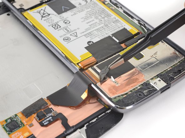
    • Use a pair of tweezers to remove the black piece of tape covering the battery connector.

    • Try your best to keep this piece of tape intact and retain it for reassembly.

  17. Questo passaggio è privo di traduzione. Aiuta a tradurlo

    : passo 17, immagine 1 di 3 : passo 17, immagine 2 di 3 : passo 17, immagine 3 di 3
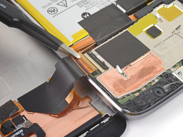
    • Use a spudger to pry up the locking tab on the display cable's ZIF connector.

    • Use a pair of tweezers to slide the display ribbon cable out of the connector.

  18. Questo passaggio è privo di traduzione. Aiuta a tradurlo

    : passo 18, immagine 1 di 1
    • Remove the screen assembly.

    • When putting your device back together, be sure to reconnect the display, turn the device on, and test all functionality before closing your device and sealing it back up.

    • During reassembly, pause here and replace the adhesive around the edges of the display if you are reusing your screen assembly.

    • After closing your device back up, stack something heavy, like a textbook or two, on top of the device for 30-60 minutes. This ensures a strong adhesive bond.

  19. Questo passaggio è privo di traduzione. Aiuta a tradurlo

    : passo 19, immagine 1 di 3 : passo 19, immagine 2 di 3 : passo 19, immagine 3 di 3
    Attrezzo utilizzato in questo passaggio:
    Tesa 61395 Tape
    $6.99
    Compra
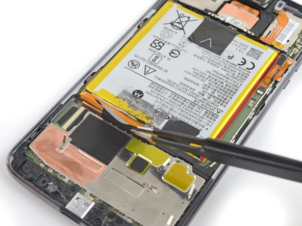
    • Use a pair of tweezers to remove the two black pieces of tape securing the battery.

    • Take care to keep these tape pieces intact so they can be reused.

    • While not crucial, this tape helps dissipate heat from the battery. They won't stick back down by themselves, but if the tape pieces are still mostly intact, re-attach them with some adhesive during reassembly.

  20. Questo passaggio è privo di traduzione. Aiuta a tradurlo

    : passo 20, immagine 1 di 3 : passo 20, immagine 2 di 3 : passo 20, immagine 3 di 3
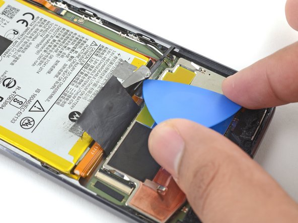
    • Use an opening pick to pry up the small black bracket covering the battery connector. It is secured with a small bit of adhesive.

    • Use a pair of tweezers or your fingers to remove the bracket.

  21. Questo passaggio è privo di traduzione. Aiuta a tradurlo

    : passo 21, immagine 1 di 2 : passo 21, immagine 2 di 2
    • Use a spudger to pry up and disconnect the battery connector.

  22. , Altoparlante: passo 22, immagine 1 di 3 , Altoparlante: passo 22, immagine 2 di 3 , Altoparlante: passo 22, immagine 3 di 3
    • Svita dall'altoparlante le due viti Torx T4 da 3 mm.

  23. : passo 23, immagine 1 di 3 : passo 23, immagine 2 di 3 : passo 23, immagine 3 di 3
    • Usa lo spudger in nylon per sollevare e rimuovere l'altoparlante dalla scocca del telefono.

  24. , Fotocamera: passo 24, immagine 1 di 2 , Fotocamera: passo 24, immagine 2 di 2
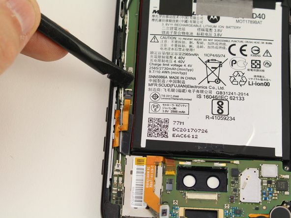
    • Inserisci l'estremità piatta dello spudger in nylon sul lato della fotocamera più vicino alla batteria.

    • Stacca la fotocamera premendo lo spudger verso il basso finché la fotocamera stessa non salta fuori.

  25. : passo 25, immagine 1 di 2 : passo 25, immagine 2 di 2
    • Inserisci l'estremità piatta dello spudger in nylon sotto l'elemento di bloccaggio nero.

    • Sblocca il cavo a nastro sollevando l'elemento di bloccaggio con lo spudger in nylon.

    • Separa la fotocamera dalla scheda tirando delicatamente verso la parte inferiore del telefono.

  26. Questo passaggio è privo di traduzione. Aiuta a tradurlo

    , Scheda madre: passo 26, immagine 1 di 3 , Scheda madre: passo 26, immagine 2 di 3 , Scheda madre: passo 26, immagine 3 di 3
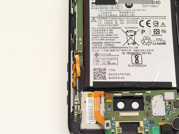
    • Using the spudger, lift up the bar on the ZIF connector that joins the ribbon cable to the control buttons.

  27. Questo passaggio è privo di traduzione. Aiuta a tradurlo

    : passo 27, immagine 1 di 3 : passo 27, immagine 2 di 3 : passo 27, immagine 3 di 3
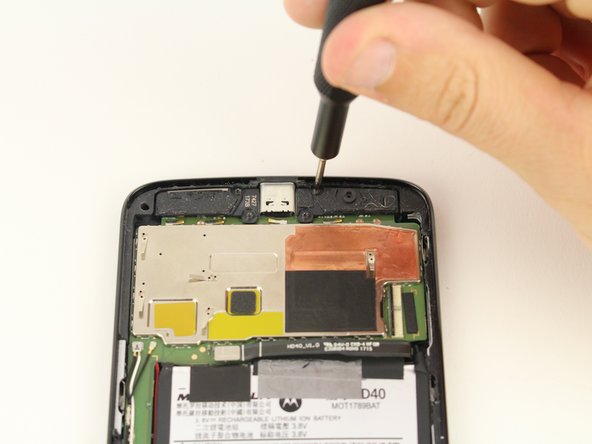
    • Unscrew four 1.8mm T4 screws from the speakers and remove from the motherboard.

  28. : passo 28, immagine 1 di 3 : passo 28, immagine 2 di 3 : passo 28, immagine 3 di 3
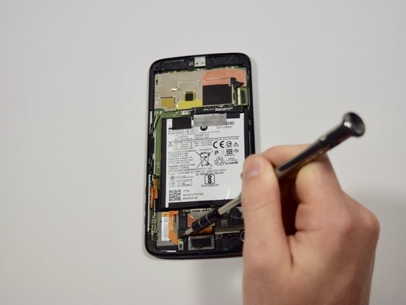
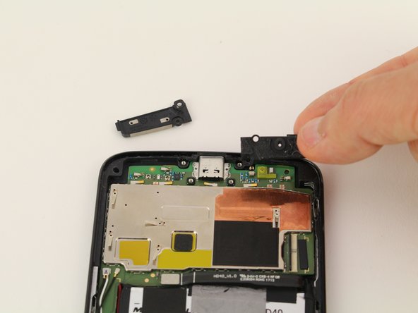
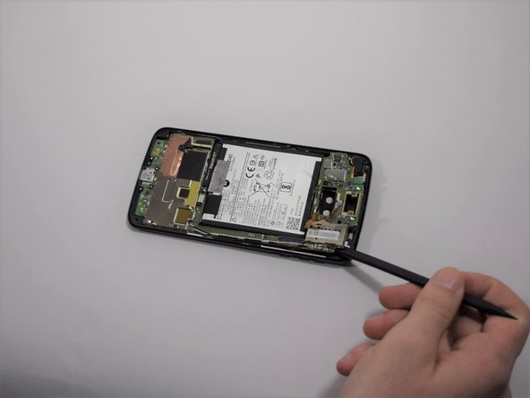
    • Inserisci l'estremità piatta dello spudger in nylon sotto il bordo del telefono vicino alla fotocamera.

    • Solleva delicatamente la scheda madre dal telefono finché non è alzata quanto basta per poter infilare un dito tra la scheda stessa il telefono.

    • Con le dita, stacca delicatamente il resto della scheda madre dal telefono.

    • Fai molta attenzione nell'usare le dita per staccare completamente la scheda madre, perché questa si può rompere facilmente.

  29. Questo passaggio è privo di traduzione. Aiuta a tradurlo

    : passo 29, immagine 1 di 3 : passo 29, immagine 2 di 3 : passo 29, immagine 3 di 3
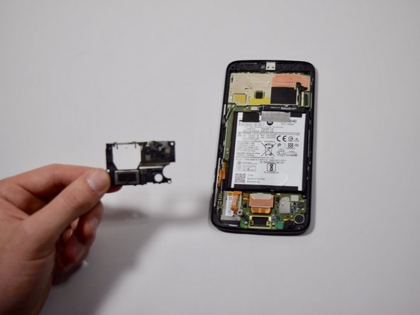
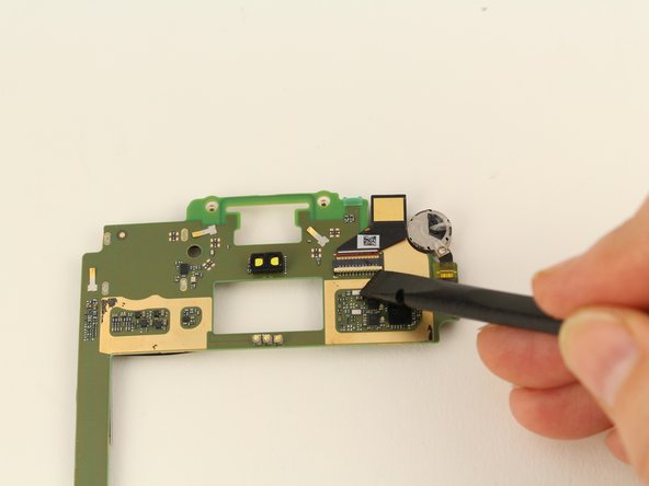
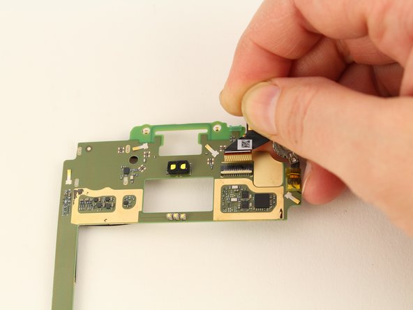
    • Flip the motherboard over.

    • Use the black nylon spudger to lift the white bar of the ZIF connector in the upper right corner.

    • Pull the front facing camera out from the ZIF connector and away from the motherboard.

Linea Traguardo

Sarah Westberg

Membro da: 03/11/19

23.348 Reputazione

70 Guide realizzate

Team

iFixit Membro di iFixit

Staff

136 Membri

17.420 Guide realizzate

0 Commenti

Aggiungi Commento

Visualizza Statistiche:

Ultime 24 Ore: 0

Ultimi 7 Giorni: 0

Ultimi 30 Giorni: 14

Tutti i Tempi: 736