Questa versione può contenere modifiche errate. Passa all'ultima istantanea verificata.
Cosa ti serve
-
-
Rimuovere le otto viti con testa a croce da 4 mm che fissano il case inferiore al MacBook.
-
-
-
Mediante l'estremità piatta di un inseritore, sollevare il connettore del cavo della batteria dal connettore femmina sulla scheda logica tirandolo verso l'alto.
-
-
-
Rimuovere le viti seguenti dal lato con unità ottica della presa posteriore:
-
Due viti Torx T8 da 10 mm
-
Due viti con testa a croce da 5 mm
-
-
Questo passaggio è privo di traduzione. Aiuta a tradurlo
-
Use the flat end of a spudger to pry the AirPort/Bluetooth ribbon cable up off the logic board.
-
-
Questo passaggio è privo di traduzione. Aiuta a tradurlo
-
Use a spudger to pry the fan connector straight up and out of its socket on the logic board.
-
-
Questo passaggio è privo di traduzione. Aiuta a tradurlo
-
Remove the following three screws securing the fan to the upper case:
-
One 7.1 mm Phillips screw.
-
Two 5 mm Phillips screws.
-
Lift the fan out of the upper case.
-
-
Questo passaggio è privo di traduzione. Aiuta a tradurlo
-
Carefully pry the delicate rear speaker connector up off the logic board. These small L/R speaker connectors are quite easily broken.
-
-
Questo passaggio è privo di traduzione. Aiuta a tradurlo
-
Use the flat end of a spudger to pry the optical drive connector up off the logic board.
-
-
Questo passaggio è privo di traduzione. Aiuta a tradurlo
-
Use a spudger to pry the right speaker connector and sleep LED connector up off the logic board.
-
-
Questo passaggio è privo di traduzione. Aiuta a tradurlo
-
Use the flat end of a spudger to pry the trackpad ribbon cable connector up off the logic board.
-
-
Questo passaggio è privo di traduzione. Aiuta a tradurlo
-
Use your fingernail to flip up the locking flap on the ZIF socket for the keyboard ribbon cable.
-
Use the tip of a spudger to slide the keyboard ribbon cable out of its socket.
-
-
Questo passaggio è privo di traduzione. Aiuta a tradurlo
-
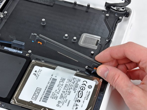
Use the flat end of a spudger to pry the hard drive cable connector up off the logic board.
-
-
Questo passaggio è privo di traduzione. Aiuta a tradurlo
-
Use a spudger to pry the left speaker connector and microphone connector up off the logic board.
-
-
-
Questo passaggio è privo di traduzione. Aiuta a tradurlo
-
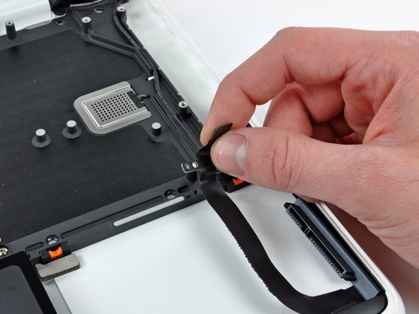
Grab the plastic pull tab secured to the display data cable lock and rotate it toward the DC-In side of the computer.
-
-
Questo passaggio è privo di traduzione. Aiuta a tradurlo
-
Gently pull the display data cable connector away from its socket on the logic board.
-
-
Questo passaggio è privo di traduzione. Aiuta a tradurlo
-
Remove the six 4.1 to 4.4 mm T6 Torx screws securing the logic board to the upper case.
-
Remove the two 4.1 to 4.5 mm T6 Torx screws securing the MagSafe board to the upper case.
-
On some models, these screws may be T7. Be careful not to strip away the head with a smaller bit.
-
-
Questo passaggio è privo di traduzione. Aiuta a tradurlo
-
Lift the side of the logic board opposite the ports out of the upper case.
-
Rotate the logic board away from the upper case until the ports clear the lip molded in the upper case.
-
Pull the logic board and MagSafe board away from the edge of the upper case as one piece.
-
-
Questo passaggio è privo di traduzione. Aiuta a tradurlo
-
Remove the two Phillips screws securing the hard drive bracket to the upper case.
-
Remove the hard drive bracket from the upper case.
-
-
Questo passaggio è privo di traduzione. Aiuta a tradurlo
-
Lift the free side of the hard drive and pull it away from the side of the upper case.
-
-
Questo passaggio è privo di traduzione. Aiuta a tradurlo
-
Disconnect the hard drive by pulling the hard drive cable connector away from its socket on the hard drive.
-
-
Questo passaggio è privo di traduzione. Aiuta a tradurlo
-
Remove the single 3.1 mm Phillips screw securing the hard drive cable to the upper case.
-
Lift the hard drive cable out of the upper case.
-
-
Questo passaggio è privo di traduzione. Aiuta a tradurlo
-
Remove two 5 mm Tri-Wing screws securing the battery to the upper case near the battery connector.
-
-
Questo passaggio è privo di traduzione. Aiuta a tradurlo
-
Use the tip of a spudger to carefully peel back the finger of the warning label to reveal a hidden Tri-Wing screw.
-
Remove the 5 mm Tri-Wing screw securing the battery to the upper case.
-
-
Questo passaggio è privo di traduzione. Aiuta a tradurlo
-
Remove three 3.1 mm Phillips screws securing the battery near the edge of the upper case.
-
-
Questo passaggio è privo di traduzione. Aiuta a tradurlo
-
Lift the battery near its connector and remove it from the upper case.
-
-
Questo passaggio è privo di traduzione. Aiuta a tradurlo
-
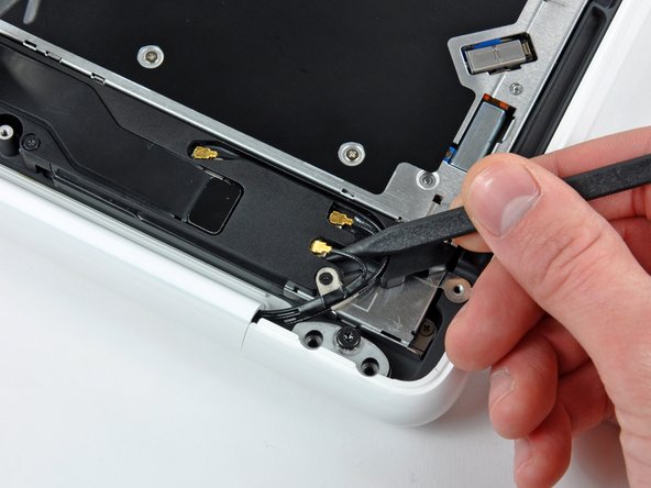
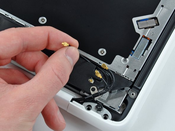
Use the tip of a spudger to pry the AirPort/Bluetooth antenna connectors (three total) up off the AirPort/Bluetooth board.
-
If necessary, de-route the long antenna cable from its slot in the rear speaker housing.
-
-
Questo passaggio è privo di traduzione. Aiuta a tradurlo
-
Remove the single 3 mm Phillips screw securing the antenna ground straps to the rear speaker housing.
-
-
Questo passaggio è privo di traduzione. Aiuta a tradurlo
-
Remove the single 2.2 mm Phillips screw inserted horizontally into the side of the optical drive.
-
-
Questo passaggio è privo di traduzione. Aiuta a tradurlo
-
Remove the single 12 mm Phillips screw securing the rear speaker to the upper case.
-
-
Questo passaggio è privo di traduzione. Aiuta a tradurlo
-
Remove the rear speaker assembly from your MacBook.
-
-
Questo passaggio è privo di traduzione. Aiuta a tradurlo
-
Remove the single 4.5 mm Phillips screw securing the inner edge of the optical drive to the upper case.
-
-
Questo passaggio è privo di traduzione. Aiuta a tradurlo
-
Remove the two 2.5 mm Phillips screws securing the optical drive to the upper case near the optical drive opening.
-
-
Questo passaggio è privo di traduzione. Aiuta a tradurlo
-
Lift the optical drive near its connector and pull it away from the upper case to remove it from the computer.
-
-
Questo passaggio è privo di traduzione. Aiuta a tradurlo
-
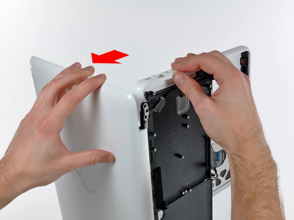
Open your MacBook so the display is perpendicular to the upper case.
-
Place your opened MacBook on a table as pictured.
-
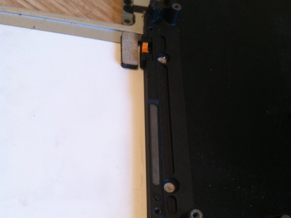
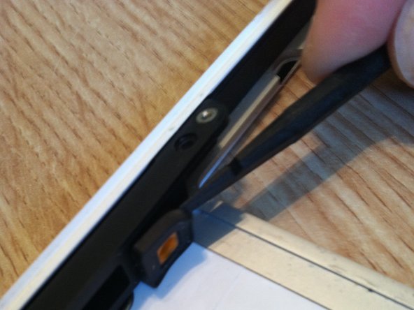
While holding the display and upper case together with your left hand, remove the remaining T8 Torx screw from the lower display bracket.
-
Before retightening the T8 Torx screws, close the display and adjust it so that the back edges of the upper case and display are aligned and the gaps at the ends of the hinge are equal.
-
-
Questo passaggio è privo di traduzione. Aiuta a tradurlo
-
Remove the last remaining T8 Torx screw securing the display to the upper case.
-
-
Questo passaggio è privo di traduzione. Aiuta a tradurlo
-
Grab the upper case with your right hand and rotate it slightly toward the top of the display so the upper display bracket clears the edge of the upper case.
-
Rotate the display slightly away from the upper case.
-
-
Questo passaggio è privo di traduzione. Aiuta a tradurlo
-
Lift the display up and away from the upper case, minding any brackets or cables that may get caught.
-
-
Questo passaggio è privo di traduzione. Aiuta a tradurlo
-
There are four orange and black rubber inserts that the hard drive sits in. One side has full circles and the other side has half circles. (The other side of the half circles are located on the hard drive bracket that was previously removed).
-
The new upper case may not have these inserts. Be sure to remove them from the old and insert into the new.
-
The inserts are easily pried out with a spudger or a flat tipped screwdriver. They are not glued in, but instead have notched sides to hold them in place.
-
-
Questo passaggio è privo di traduzione. Aiuta a tradurlo
-
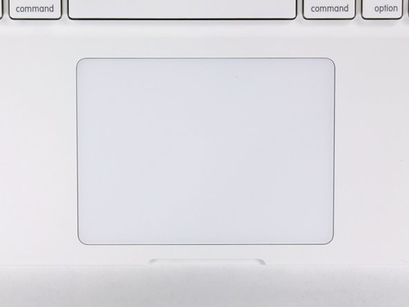
Remove the four 1.3 mm Phillips screws securing the upper edge of the trackpad to the upper case.
-
-
Questo passaggio è privo di traduzione. Aiuta a tradurlo
-
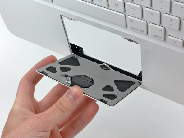
Carefully tilt the trackpad away from the keyboard side of the upper case.
-
Pull the trackpad away from its opening in the upper case to clear the two mounting tabs on its lower edge.
-
-
Questo passaggio è privo di traduzione. Aiuta a tradurlo
-
Remove the 1 mm T6 Torx set screw near the front edge of the upper case.
-
-
Questo passaggio è privo di traduzione. Aiuta a tradurlo
-
Reinstall the T6 Torx set screw until it is flush with the aluminum bracket surrounding the trackpad.
-
Place the trackpad back into its void in the upper case, being sure the lower tabs are inserted underneath the keyboard side of the upper case.
-
-
Questo passaggio è privo di traduzione. Aiuta a tradurlo
-
Reinstall the four silver Phillips screws securing the trackpad to its steel brackets.
-
Loosen all four silver screws about 1/16th of a turn.
-
Flip the upper case over and adjust the position of the trackpad until the gap between the trackpad and the upper case is evenly spaced around the perimeter of the trackpad.
-
Tighten the four silver screws to hold the trackpad in place.
-
-
Questo passaggio è privo di traduzione. Aiuta a tradurlo
-
While repeatedly pressing the trackpad to simulate clicking, tighten the T6 Torx set screw until the trackpad no longer wiggles freely.
-


Annulla: non ho completato questa guida.
Altre 197 persone hanno completato questa guida.

25 Commenti
Some of the screws are extremely tight, I stripped at least 6 Phillips screws during the upper case replacement.
I used the iFixit 54 bit kit and found that the Phillips 000 bit fits the screws better than the recommended 00 bit. When loosening or tightening I use plenty of downward pressure to keep the bit from rising out of the screw head and damaging it. The torx screws are so much easier to work with and I wonder why they don't use only those.
Definitely only use unworn, appropriately sized drivers when going into any Mac or iPhone. If the driver starts to slip, stop and access the situation. That said, I have encountered many screws with damaged screw heads. I usually first try the “rubber band” trick to loosen the ruined screw. If that doesn’t work, I often resort to using a dremel tool to cut a slot in the screw (while protecting everything from the debris generated). In all cases, be careful - one slip can do a lot of damage.
Lance J -