Questa versione può contenere modifiche errate. Passa all'ultima istantanea verificata.
Cosa ti serve
-
-
Svita le seguenti viti che fissano la scocca inferiore a quella superiore:
-
Tre viti a croce Phillips da 13,5 mm.
-
Sette viti a croce Phillips da 3 mm.
-
-
-
Se presente, afferra la linguetta di plastica attaccata al connettore della batteria e tirala verso il lato anteriore del dispositivo. Per i modelli di fine 2011, il connettore non avrà una linguetta ed è semplicemente una spina che si inserisce direttamente nella scheda madre, per rimuoverla tirala verso l'alto.
-
-
Questo passaggio è privo di traduzione. Aiuta a tradurlo
-
Use the flat end of a spudger to lift the right fan connector out of its socket on the logic board.
-
-
Questo passaggio è privo di traduzione. Aiuta a tradurlo
-
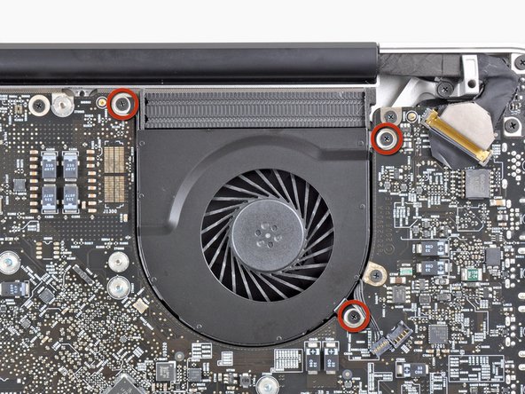
Remove the three 3.1 mm Phillips screws securing the right fan to the logic board.
-
-
Questo passaggio è privo di traduzione. Aiuta a tradurlo
-
Remove the right fan from the upper case, minding its cable that may get caught.
-
-
Questo passaggio è privo di traduzione. Aiuta a tradurlo
-
Use the flat end of a spudger to lift the left fan connector out of its socket on the logic board.
-
-
Questo passaggio è privo di traduzione. Aiuta a tradurlo
-
Remove the three 3.1 mm Phillips screws securing the left fan to the logic board.
-
Remove the left fan from the upper case, minding its cable that may get caught.
-
-
Questo passaggio è privo di traduzione. Aiuta a tradurlo
-
Use the tip of a spudger or your fingernail to flip up the retaining flap on the keyboard backlight ribbon cable.
-
Pull the keyboard backlight ribbon cable out of its socket.
-
-
-
Questo passaggio è privo di traduzione. Aiuta a tradurlo
-
Use the tip of a spudger to push the small plastic cable retainer away from the camera cable socket for enough clearance to remove the camera cable.
-
-
Questo passaggio è privo di traduzione. Aiuta a tradurlo
-
Pull the camera cable toward the optical drive opening to disconnect it from the logic board.
-
-
Questo passaggio è privo di traduzione. Aiuta a tradurlo
-
Use the flat end of a spudger to pry the optical drive connector up and out of its socket on the logic board.
-
-
Questo passaggio è privo di traduzione. Aiuta a tradurlo
-
Use the flat end of a spudger to lift the subwoofer & right speaker connector out of its socket on the logic board.
-
-
Questo passaggio è privo di traduzione. Aiuta a tradurlo
-
Use the tip of a spudger or your fingernail to flip up the retaining flap on the IR sensor ribbon cable socket.
-
Pull the IR sensor ribbon cable out of its socket.
-
-
Questo passaggio è privo di traduzione. Aiuta a tradurlo
-
Remove the following four screws:
-
Two 3.5 mm Phillips screws
-
Two 1.6 mm Phillips screws
-
Remove both connector shields from the logic board.
-
-
Questo passaggio è privo di traduzione. Aiuta a tradurlo
-
Use the flat end of a spudger to pry the trackpad connector up and out of its socket on the logic board.
-
-
Questo passaggio è privo di traduzione. Aiuta a tradurlo
-
Use your fingernail to flip up the retaining flap on the keyboard ribbon cable socket.
-
Pull the keyboard ribbon cable out of its socket.
-
-
Questo passaggio è privo di traduzione. Aiuta a tradurlo
-
Use your fingernail to flip up the retaining flap on the express card cage ribbon cable socket.
-
Pull the express card cage ribbon cable out of its socket.
-
-
Questo passaggio è privo di traduzione. Aiuta a tradurlo
-
Use the flat end of a spudger to lift the hard drive cable connector up and out of its socket on the logic board.
-
-
Questo passaggio è privo di traduzione. Aiuta a tradurlo
-
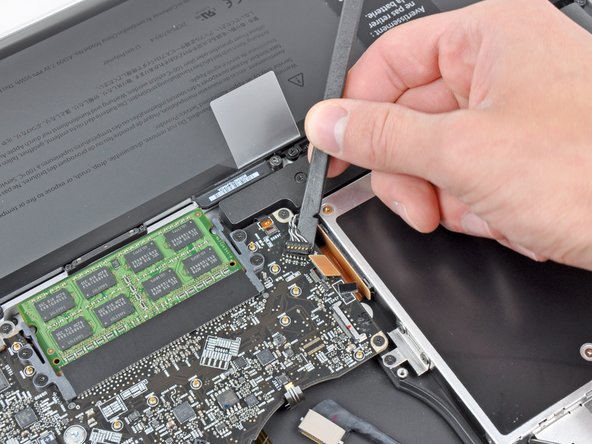
Use the tip of a spudger or your fingernail to flip up the retaining flap on the battery indicator cable socket.
-
Pull the battery indicator ribbon cable out of its socket.
-
-
Questo passaggio è privo di traduzione. Aiuta a tradurlo
-
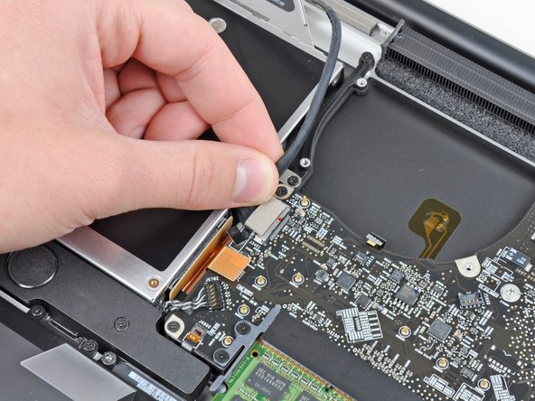
Lift the black plastic flap attached to the display data cable retainer and rotate it toward the DC-In side of the MacBook.
-
Pull the display data cable out of its socket.
-
-
Questo passaggio è privo di traduzione. Aiuta a tradurlo
-
Remove the following eight screws securing the logic board and DC-In board to the upper case:
-
Six 3.2 mm Phillips screws
-
Two 7.6 mm Phillips screws
-
-
Questo passaggio è privo di traduzione. Aiuta a tradurlo
-
Lift the logic board assembly from the side nearest the optical drive and lift it away from the upper case.
-
Carefully pull the ports and DC-In board away from the side of the upper case and remove the logic board assembly, minding any cables that may get caught.
-
-
Questo passaggio è privo di traduzione. Aiuta a tradurlo
-
Remove the eight 8.3 mm Phillips screws securing the heat sink to the logic board.
-
-
Questo passaggio è privo di traduzione. Aiuta a tradurlo
-
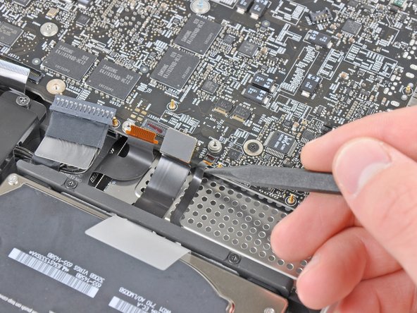
Squeeze the heat sink thermal sensor cable between your thumb and the tip of a spudger.
-
Lift the spudger upward to lift the thermal sensor connector out of its socket on the logic board.
-


Annulla: non ho completato questa guida.
Altre 33 persone hanno completato questa guida.

10 Commenti
After compleating this repair , my mac had the normal hard drive noise then a chime did not even grey screen . almost instantly I smelt fire and saw smoke pouring out of the case.. maac was on battery at the time .. I opened it up and disconected the battery and then I saw the video display cable (Step 21 ) it had glowing embers on the tape and tottally melted one side of it ... the connector to the logic board has black marks , but i do not know if the damage is extened to the logic board or if I can get away with a new dispay data cable , dont even know where to source one here in NZ .. any help would be great
I completed this guide. When I finished the macbook would not turn on => PANIC
I went over and the problem was the keyboard cable. The Step 17 is a little difficult in reverse. Pay special atention at the correct position of the keyboard ribbon cable.
It was a little scare. Otherwise all perfect! Thank you very much!
Successfully changed the thermal paste by following this guide. My MacBook Pro had some issues after I put it back together because of loose and improperly seated cables. In my case, the display cable wasn't seated properly and the IR-sensor cable was loose. So if your machine doesn't turn on, or something seems to be working incorrectly, it's definitely worth double checking the cables.
did changing the thermal paste lower your temps? what was it before, what is it now? thanks for sharing.
B S -
Yes B S, the temps will be lower. Apple is known to put only a tiny amount or bad quality thermal paste on their machines, so even is a Mac is brand new, temperatures will be better if the thermal paste is replaced. I have replaced thermal paste on numerous computers and have never regretted it :)
Tsaku -