Questa versione può contenere modifiche errate. Passa all'ultima istantanea verificata.
Cosa ti serve
-
-
Rimuovi le dieci viti seguenti, che fissano il case inferiore a quello superiore:
-
Tre viti con testa a croce Phillips da 13,5 (14,1) mm.
-
Sette viti con testa a croce da 3 mm.
-
-
-
Rimuovi le due viti Tri-point da 7,4 mm che fissano la batteria al case superiore.
-
Nota: per alcune riparazioni (ad es. il disco rigido), non occorre rimuovere la batteria, ma ciò previene qualsiasi cortocircuito accidentale dei componenti elettronici sulla scheda madre. Se decidi di non rimuovere la batteria, opera con cautela poiché alcune parti della scheda madre potrebbero essere percorse da corrente elettrica.
-
-
-
Inclina la batteria allontanandola dalla scheda logica finché sarà possibile accedere al connettore del cavo della batteria.
-
Rimuovi il connettore del cavo della batteria dal suo zoccolo sulla scheda logica e rimuovi la batteria dal case superiore.
-
Carica al 100% e poi tieni sotto carica almeno altre due ore. Quindi stacca l'alimentazione e usa il laptop normalmente per farlo scaricare. All'avviso di batteria in esaurimento, salva il lavoro corrente e tieni acceso il MacBook finché non si iberna perché è scarico. Aspetta almeno altre 5 ore, poi carica il laptop ininterrottamente fino al 100%.
-
Se noti qualsiasi problema o comportamento inusuale dopo l'installazione di una nuova batteria, può essere necessario resettare l'SMC del tuo MacBook.
-
-
Questo passaggio è privo di traduzione. Aiuta a tradurlo
-
Use the flat end of a spudger to carefully pry the AirPort/Bluetooth ribbon cable up off its socket on the logic board.
-
-
Questo passaggio è privo di traduzione. Aiuta a tradurlo
-
Pull the camera cable connector straight out of its socket on the logic board.
-
-
Questo passaggio è privo di traduzione. Aiuta a tradurlo
-
Use the tip of a spudger to pry the three antenna connectors up off the AirPort/Bluetooth board.
-
-
Questo passaggio è privo di traduzione. Aiuta a tradurlo
-
De-route all three antenna cables from their channels in the AirPort/Bluetooth housing.
-
De-route the camera cable from its channel in the AirPort/Bluetooth housing.
-
-
Questo passaggio è privo di traduzione. Aiuta a tradurlo
-
Remove the following two screws securing the AirPort/Bluetooth housing to the upper case:
-
One 3.8 mm Phillips
-
One 8.6 mm Phillips
-
-
Questo passaggio è privo di traduzione. Aiuta a tradurlo
-
Remove the AirPort/Bluetooth assembly from the upper case, minding any cables that may get caught.
-
-
Questo passaggio è privo di traduzione. Aiuta a tradurlo
-
Remove the 8.6 mm Phillips screw securing the antenna/camera cable retainer to the upper case.
-
Remove the antenna/camera cable retainer from the upper case.
-
-
-
Questo passaggio è privo di traduzione. Aiuta a tradurlo
-
Remove two of the three 6 mm T6 Torx screws securing the right side of the display to the upper case.
-
-
Questo passaggio è privo di traduzione. Aiuta a tradurlo
-
Grab the plastic pull tab secured to the display data cable lock and rotate it toward the DC-In side of the computer.
-
Pull the display data cable straight out of its socket on the logic board.
-
-
Questo passaggio è privo di traduzione. Aiuta a tradurlo
-
Remove the 8.6 mm Phillips screw securing the display data cable retainer to the upper case.
-
Remove the display data cable retainer from the upper case.
-
-
Questo passaggio è privo di traduzione. Aiuta a tradurlo
-
Remove two of the three 6 mm T6 Torx screws securing the left side of the display to the upper case.
-
-
Questo passaggio è privo di traduzione. Aiuta a tradurlo
-
Open your MacBook Pro so the display is perpendicular to the upper case.
-
Place your opened MacBook Pro on a table as pictured.
-
While holding the display and upper case together with your left hand, remove the remaining T6 Torx screw from the upper display bracket.
-
-
Questo passaggio è privo di traduzione. Aiuta a tradurlo
-
Remove the last remaining T6 Torx screw securing the display to the upper case.
-
-
Questo passaggio è privo di traduzione. Aiuta a tradurlo
-
Grab the upper case with your right hand and rotate it slightly toward the top of the display so the upper display bracket clears the edge of the upper case.
-
Rotate the display slightly away from the upper case.
-
Lift the display up and away from the upper case, minding any brackets or cables that may get caught.
-
-
Questo passaggio è privo di traduzione. Aiuta a tradurlo
-
Insert the tip of a spudger underneath the black rubber gasket at the bottom right corner of the display assembly.
-
Gently pry the wide edge of the gasket up from the back case.
-
-
Questo passaggio è privo di traduzione. Aiuta a tradurlo
-
Starting with the freed corner, pull the rubber gasket off the right side of the display assembly.
-
-
Questo passaggio è privo di traduzione. Aiuta a tradurlo
-
Continue pulling the display gasket off the display assembly across the top edge.
-
-
Questo passaggio è privo di traduzione. Aiuta a tradurlo
-
Continue pulling the display gasket off the display assembly down the left side.
-
Pull the gasket off the bottom edge of the display to completely free it and set it aside.
-
-
Questo passaggio è privo di traduzione. Aiuta a tradurlo
-
With the heat gun set to low, start by heating the metal bezel surrounding the LCD.
-
-
Questo passaggio è privo di traduzione. Aiuta a tradurlo
-
Carefully insert a guitar pick between the top right corner of the bezel and the display assembly.
-
Use the guitar pick to gently pry up the adhesive along the top edge securing the bezel to the display assembly.
-
-
Questo passaggio è privo di traduzione. Aiuta a tradurlo
-
Work along the top right edge of the display assembly, carefully prying the adhesive up with the guitar pick. Stop when you get to the iSight camera.
-
-
Questo passaggio è privo di traduzione. Aiuta a tradurlo
-
Use a heat gun to soften the adhesive under the bezel along the left and top left edges of the display.
-
-
Questo passaggio è privo di traduzione. Aiuta a tradurlo
-
Carefully insert a guitar pick between the top left corner of the bezel and the display assembly.
-
Use the guitar pick to gently pry up the adhesive along the left edge securing the bezel to the display assembly.
-
-
Questo passaggio è privo di traduzione. Aiuta a tradurlo
-
Repeat the procedures in the two previous steps for the right edge of the display.
-
-
Questo passaggio è privo di traduzione. Aiuta a tradurlo
-
Work along the top left edge of the display assembly, carefully prying the adhesive up with the guitar pick. Stop when you get to the iSight camera.
-
-
Questo passaggio è privo di traduzione. Aiuta a tradurlo
-
Wedge a guitar pick in between the bezel and display assembly near the inner bottom left corner.
-
Work along the inner bottom left edge of the display assembly, carefully prying the adhesive up with the guitar pick.
-
Continue prying along the inner bottom edge to release the adhesive securing the bezel to the display assembly.
-
-
Questo passaggio è privo di traduzione. Aiuta a tradurlo
-
Use a guitar pick to gently lift the bottom right corner of the bezel.
-
-
Questo passaggio è privo di traduzione. Aiuta a tradurlo
-
Slowly lift the bottom edge of the bezel and gently rotate it out of the display.
-
-
Questo passaggio è privo di traduzione. Aiuta a tradurlo
-
Lifting the left edge of the clutch cover, gently rock it back and forth on its long axis while pulling it away from the display.
-
Remove the clutch cover from the display, minding any cables that may get caught.
-
-
Questo passaggio è privo di traduzione. Aiuta a tradurlo
-
Remove the six 2.9 mm Phillips screws securing the LCD panel to the display assembly.
-
-
Questo passaggio è privo di traduzione. Aiuta a tradurlo
-
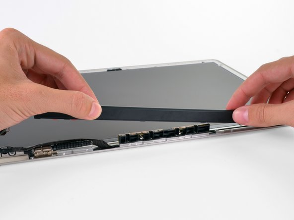
Pull the LCD toward the top edge of the display assembly to slide the inverter board along its lower edge out of the recess in the aluminum display assembly.
-
-
Questo passaggio è privo di traduzione. Aiuta a tradurlo
-
Peel the piece of tape covering the display data cable connector away from the edge closest to the LCD.
-
-
Questo passaggio è privo di traduzione. Aiuta a tradurlo
-
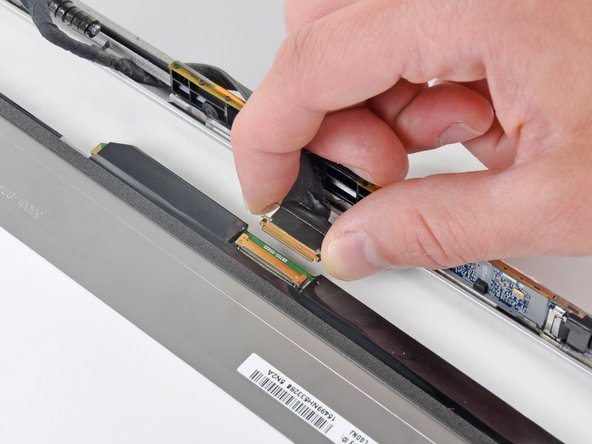
Use the tip of a spudger to flip up the thin steel retaining clip securing the display data cable to its socket on the LCD.
-
Pull the display data cable straight away from its socket on the LCD.
-
Lift the LCD out of the display assembly and set it aside.
-


Annulla: non ho completato questa guida.
Altre 12 persone hanno completato questa guida.

2 Commenti
I had no problem with reapplying the gasket as it fits nicely into the notch.
A big THANKS to Walter! It is in deed not easy but thanks to this detailed instructions I got it working!! :)