Questa versione può contenere modifiche errate. Passa all'ultima istantanea verificata.
Cosa ti serve
-
-
Rimuovi le seguenti 10 viti a croce Phillips che fissano il case inferiore a quello superiore:
-
Sette viti da 3 mm.
-
Tre viti da 13,5 mm.
-
-
CompraAttrezzo utilizzato in questo passaggio:P6 Pentalobe Screwdriver 2009 15" MacBook Pro Battery$5.49
-
Questo passaggio è privo di traduzione. Aiuta a tradurlo
-
Use the tip of a spudger to rotate the plastic retainer away from the camera cable connector.
-
-
Questo passaggio è privo di traduzione. Aiuta a tradurlo
-
Pull the camera cable away from its socket on the logic board.
-
-
Questo passaggio è privo di traduzione. Aiuta a tradurlo
-
Peel the camera cable off the adhesive securing it to the body of the optical drive.
-
-
Questo passaggio è privo di traduzione. Aiuta a tradurlo
-
Disconnect the Bluetooth cable by pulling the male end straight away from its socket.
-
Use the flat end of a spudger to pry the Bluetooth antenna cable up from its socket on the board.
-
-
Questo passaggio è privo di traduzione. Aiuta a tradurlo
-
Remove the two 8 mm Phillips screws securing the Bluetooth/camera cable retainer to the upper case.
-
Lift the Bluetooth board/cable retainer assembly out of the upper case.
-
-
Questo passaggio è privo di traduzione. Aiuta a tradurlo
-
Remove the two 8 mm Phillips screws securing the camera cable retainer to the upper case.
-
Lift the camera cable retainer out of the upper case.
-
-
-
Questo passaggio è privo di traduzione. Aiuta a tradurlo
-
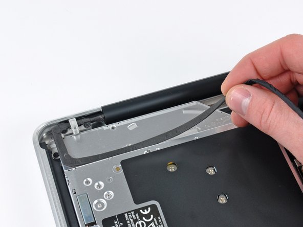
Grab the plastic pull tab secured to the display data cable lock and rotate it toward the DC-In side of the computer.
-
-
Questo passaggio è privo di traduzione. Aiuta a tradurlo
-
Remove the single 7 mm Phillips screw securing the display data cable retainer to the upper case.
-
Remove the display data cable retainer from the upper case.
-
-
Questo passaggio è privo di traduzione. Aiuta a tradurlo
-
Pull the display data cable connector straight away from its socket.
-
-
Questo passaggio è privo di traduzione. Aiuta a tradurlo
-
Remove the outer two T6 Torx screws securing both display hinges to the upper case (four screws total).
-
-
Questo passaggio è privo di traduzione. Aiuta a tradurlo
-
Open your MacBook Pro so the display is perpendicular to the upper case.
-
Place your opened MacBook Pro on a table as pictured.
-
While holding the display and upper case together with your left hand, remove the remaining T6 Torx screw from the lower display bracket.
-
-
Questo passaggio è privo di traduzione. Aiuta a tradurlo
-
Remove the last remaining T6 Torx screw securing the display to the upper case.
-
-
Questo passaggio è privo di traduzione. Aiuta a tradurlo
-
Grab the upper case with your right hand and rotate it slightly toward the top of the display so the upper display bracket clears the edge of the upper case.
-
Rotate the display slightly away from the upper case.
-
Lift the display up and away from the upper case, minding any brackets or cables that may get caught.
-
-
Questo passaggio è privo di traduzione. Aiuta a tradurlo
-
Before starting, be sure to clean the display glass with lint-free cloth moistened with a mild solution; it will make the suction cup adhere better, and will make checking for dust on reassembly easier
-
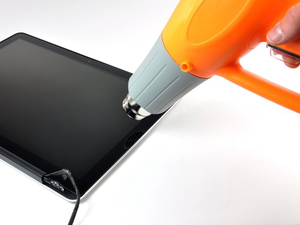
With the heat gun set to low, start by heating the outer black border near the upper right corner of the glass panel.
-
-
Questo passaggio è privo di traduzione. Aiuta a tradurlo
-
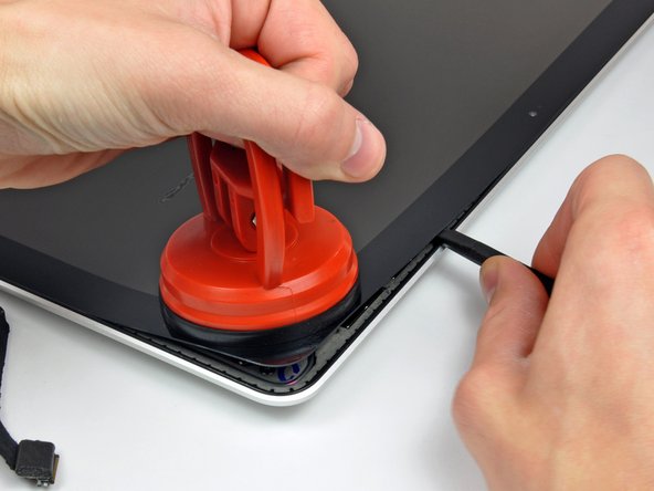
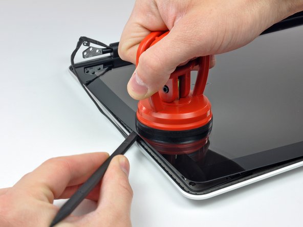
With the panel sufficiently heated, fasten a heavy-duty suction cup near the upper right corner of the display glass.
-
Slowly and gently pull the corner of the display glass up off the display assembly.
-
-
Questo passaggio è privo di traduzione. Aiuta a tradurlo
-
Gently lift the corner of the display glass enough to insert a spudger between it and the display assembly.
-
Use the flat end of a spudger to gently pry up the adhesive securing the front glass to the display.
-
Pry up the glass panel a few inches away from the upper right corner along the top and right edges of the display.
-
-
Questo passaggio è privo di traduzione. Aiuta a tradurlo
-
Use a heat gun to soften the adhesive under the black strip along the right side of the front glass panel.
-
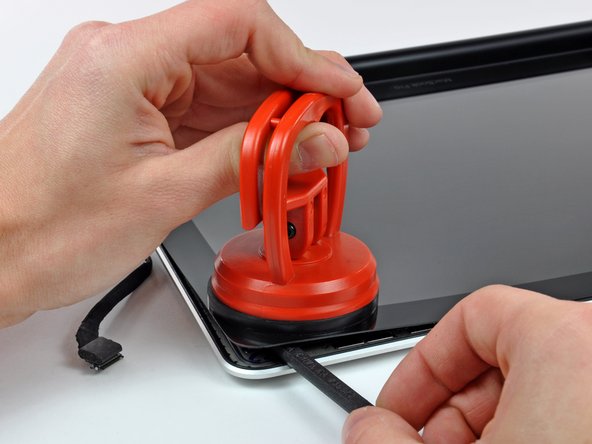
Attach a suction cup along the right side of the front glass panel.
-
Pull up on the glass panel while you use the flat end of a spudger to separate it from the rest of the display assembly.
-
Continue working along the right edge of the front display glass until it is separated from the display.
-
-
Questo passaggio è privo di traduzione. Aiuta a tradurlo
-
Use your heat gun to soften the adhesive under the black strip along the top edge of the glass display panel.
-
Attach a suction cup near the top edge of the glass display panel and use it to pull the glass panel up off the display.
-
Work along the top edge of the glass panel, carefully using the flat end of a spudger to separate the adhesive if necessary.
-
-
Questo passaggio è privo di traduzione. Aiuta a tradurlo
-
Use a heat gun to soften the adhesive under the black strip near the upper left corner of the glass display panel.
-
Attach a suction cup near the upper left corner of the glass display panel.
-
Pull up on the suction cup and use the flat end of a spudger to carefully pry the glass display panel out of the display assembly.
-
-
Questo passaggio è privo di traduzione. Aiuta a tradurlo
-
Use a heat gun to soften the adhesive under the black strip along the left side of the front glass panel.
-
Attach a suction cup along the left side of the front glass panel.
-
Pull up on the glass panel while you use the flat end of a spudger to separate it from the rest of the display assembly.
-
Continue working along the left edge of the front display glass until it is separated from the display.
-
-
Questo passaggio è privo di traduzione. Aiuta a tradurlo
-
Now that the top, left, and right edges of the glass are free from the display, slowly lift the top edge of the glass panel and gently rotate it out of the display.
-
-
Questo passaggio è privo di traduzione. Aiuta a tradurlo
-
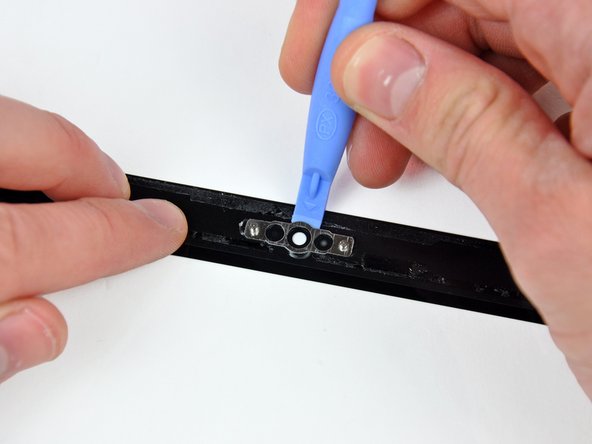
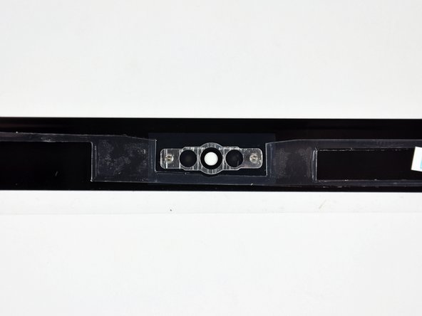
Insert the edge of a plastic opening tool between the display glass and the camera bracket, and run it around the camera bracket to separate it from the display glass.
-
-
Questo passaggio è privo di traduzione. Aiuta a tradurlo
-
To reconnect the cable, first use the tip of a spudger to remove the piece of foam tape over the camera cable ZIF socket.
-
Use the tip of a spudger to flip up the ZIF cable retainer on the camera cable socket.
-
Insert the camera cable into its socket on the camera board and use the tip of a spudger to snap down the ZIF cable retainer, locking the cable in place.
-
-
Questo passaggio è privo di traduzione. Aiuta a tradurlo
-
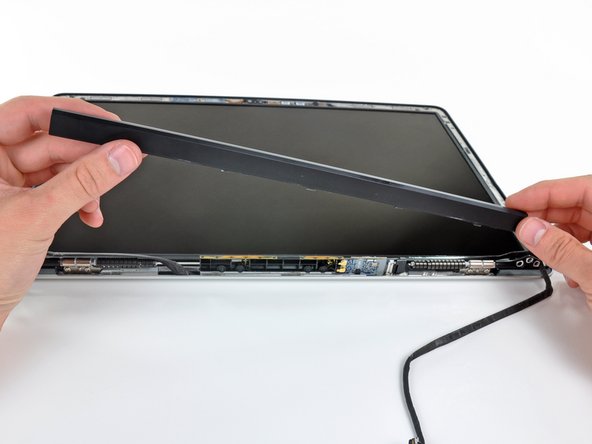
Slide the clutch cover toward the right edge of the display.
-
-
Questo passaggio è privo di traduzione. Aiuta a tradurlo
-
Starting at its far left end, rock the clutch cover along its long axis while pulling it away from the clutch hinge.
-
Working from right to left, carefully continue to release and lift the clutch along the lower edge of the display assembly.
-
Lift the clutch cover up off the front bezel and set it aside.
-
-
Questo passaggio è privo di traduzione. Aiuta a tradurlo
-
Remove the six 2.9 mm Phillips screws securing the LCD panel to the front bezel.
-
-
Questo passaggio è privo di traduzione. Aiuta a tradurlo
-
Pull the LCD toward the top edge of the display to slide the circuitry along its lower edge out of the recess in the aluminum display assembly.
-
-
Questo passaggio è privo di traduzione. Aiuta a tradurlo
-
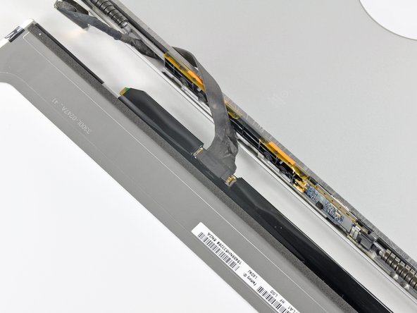
Peel the piece of tape covering the display data cable connector away from the edge closest to the LCD.
-
-
Questo passaggio è privo di traduzione. Aiuta a tradurlo
-
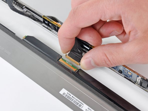
Use the tip of a spudger to flip up the thin steel retaining clip securing the display data cable to its socket on the LCD.
-
Pull the display data cable straight away from its socket on the LCD.
-
Lift the LCD out of the display assembly and set it aside.
-


Annulla: non ho completato questa guida.
Altre 34 persone hanno completato questa guida.

9 Commenti
General : Is there instruction available if you have the anti-glare displays? Or do you officially recommand to change the LCD AND THE GLASS, if we want to keep the anti-glare displays? Can we order the anti-glare displays here? Thanks! =)
I have a Macbook Pro Unibody 15" (2009) can I switch the whole display and lid with a Macbook Pro 15" (2011)and is the airport card piece for both models in the display?...
No, you can’t, because of the camera cable connector, different from the 2011 model.
Where can i get the metal frame that runs through the LCD assembly.
Same question for me!