Salta al contenuto principale

Questa versione può contenere modifiche errate. Passa all'ultima istantanea verificata.

Cosa ti serve

  1. , Case inferiore: passo 1, immagine 1 di 1
    • Rimuovi le dieci viti seguenti, che fissano il case inferiore a quello superiore:

    • Sette viti con testa a croce da 3 mm.

    • Tre viti con testa a croce da 13,5 mm.

  2. : passo 2, immagine 1 di 1
    • Solleva con entrambe le mani il case inferiore in prossimità della presa d'aria per estrarre le due levette di fissaggio al case superiore.

    • Rimuovi il case inferiore e mettilo da una parte.

  3. , Batteria: passo 3, immagine 1 di 1
    Attrezzo utilizzato in questo passaggio:
    P6 Pentalobe Screwdriver 2009 15" MacBook Pro Battery
    $5.49
    Compra
    • La batteria è fissata al case superiore mediante tre viti Pentalobe a cinque punte. È possibile rimuoverle mediante questo apposito cacciavite.

    • Se non haui un cacciavite Pentalobe, puoi usare un normale cacciavite a taglio da 1,5 mm. Verifica che la testa del cacciavite piatto si inserisca fermamente fra due delle cinque punte della testa della vite prima di iniziare a svitare, altrimenti rischi di spanare la testa della vite.

    • Se la punta del cacciavite si muove troppo nella testa della vite, prima di procedere prova punte più grandi finché non si inseriscono senza gioco.

    • Non occorre necessariamente seguire i passaggi da 3 a 7 per rimuovere la batteria per sostituire il disco rigido. Tuttavia, si consiglia di rimuovere tutte le fonti di alimentazione dai componenti elettronici prima di operare su di essi.

  4. : passo 4, immagine 1 di 1
    • Rimuovi le due viti di sicurezza Pentalobe esposte lungo il bordo superiore della batteria.

  5. : passo 5, immagine 1 di 1
    • Usa la punta di uno spudger per piegare all'indietro l'aletta dell'adesivo che avverte di non rimuovere la batteria "Warning: Do not remove the battery" mentre rimuovi le viti Pentalobe nascoste sotto.

  6. : passo 6, immagine 1 di 2 : passo 6, immagine 2 di 2
    • Solleva la batteria tirandola dalla linguetta di plastica e falla scorrere lontano dal bordo lungo del case superiore.

    • Non tentare ancora di rimuovere completamente la batteria.

  7. : passo 7, immagine 1 di 1
    • Inclina la batteria all'indietro quanto basta per rendere accessibile il connettore del cavo della batteria.

    • Tira via il connettore del cavo della batteria dallo zoccolo sulla scheda logica e rimuovi la batteria dal case superiore.

    • Se stai installando una nuova batteria, dovresti calibrarla non appena è possibile.

  8. Questo passaggio è privo di traduzione. Aiuta a tradurlo

    : passo 8, immagine 1 di 2 : passo 8, immagine 2 di 2
    • Apple sticks a small strip of clear plastic with adhesive applied to one side to the logic board behind the camera cable connector to keep it in its socket. When moving it out of the way, be sure not to break any surface-mount components off the logic board.

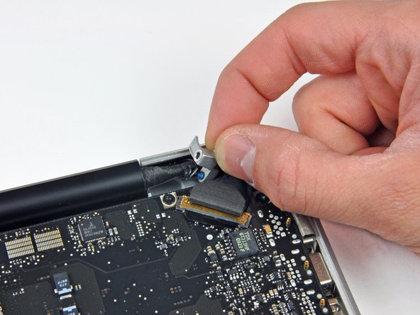
    • Hold the end of the cable retainer down with one finger while you use the tip of a spudger to slightly lift the other end and rotate it away from the camera cable connector.

    • Pull the camera cable away from its socket on the logic board.

    • Pull the connector parallel to the face of the logic board, not straight up.

  9. Questo passaggio è privo di traduzione. Aiuta a tradurlo

    : passo 9, immagine 1 di 1
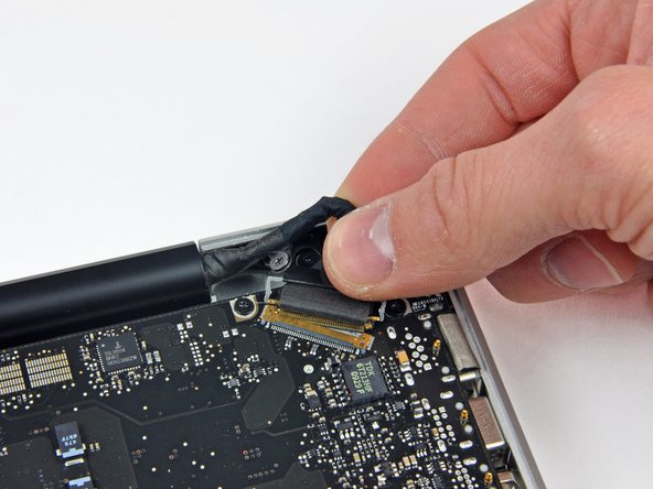
    • Peel the camera cable off the adhesive securing it to the optical drive.

  10. Questo passaggio è privo di traduzione. Aiuta a tradurlo

    : passo 10, immagine 1 di 2 : passo 10, immagine 2 di 2
    • This step is only required if you have an anti-glare display. If you have a glossy display, skip to step 12.

    • Disconnect the Bluetooth cable by pulling the male end straight away from its socket.

    • Pull the connector parallel to the face of the logic board, not straight up.

    • Use the flat end of a spudger to pry the Bluetooth antenna cable from its socket on the board.

  11. Questo passaggio è privo di traduzione. Aiuta a tradurlo

    : passo 11, immagine 1 di 2 : passo 11, immagine 2 di 2
    • This step is only required if you have an anti-glare display.

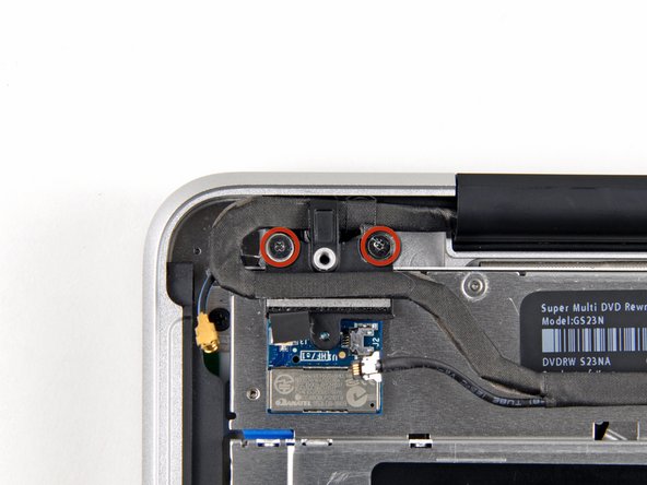
    • Remove the two 8 mm Phillips screws securing the Bluetooth/camera cable retainer to the upper case.

    • One of the screws may remain captive in the Bluetooth/camera cable ground loop. If replacing the display, be sure to transfer this screw to the new unit.

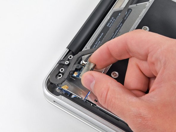
    • Lift the Bluetooth board/cable retainer assembly out of the upper case.

  12. Questo passaggio è privo di traduzione. Aiuta a tradurlo

    : passo 12, immagine 1 di 2 : passo 12, immagine 2 di 2
    • This step is only for glossy display machines. If you have an anti-glare display, skip this step.

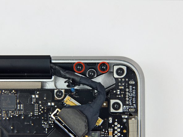
    • Remove the two 8 mm Phillips screws securing the camera cable retainer to the upper case.

    • One of the screws may remain captive in the camera cable ground loop. If replacing the display, be sure to transfer this screw to the new unit.

    • Lift the camera cable retainer out of the upper case.

  13. Questo passaggio è privo di traduzione. Aiuta a tradurlo

    : passo 13, immagine 1 di 2 : passo 13, immagine 2 di 2
    • Remove the single 7 mm Phillips screw securing the display data cable retainer to the upper case.

    • This screw may remain captive in the display data cable ground loop. If replacing the display, be sure to transfer this screw to the new unit.

    • Remove the display data cable retainer from the upper case.

  14. Questo passaggio è privo di traduzione. Aiuta a tradurlo

    : passo 14, immagine 1 di 2 : passo 14, immagine 2 di 2
    • Grab the plastic pull tab secured to the display data cable lock and rotate it toward the DC-in side of the computer.

    • Pull the display data cable connector straight away from its socket.

    • Make sure to pull the connector parallel to the face of the logic board, not straight up from its socket.

  15. Questo passaggio è privo di traduzione. Aiuta a tradurlo

    : passo 15, immagine 1 di 2 : passo 15, immagine 2 di 2
    • Remove the outer two T6 Torx screws securing both display hinges to the upper case (four screws total).

  16. Questo passaggio è privo di traduzione. Aiuta a tradurlo

    : passo 16, immagine 1 di 1
    • Open your MacBook so the display is perpendicular to the upper case.

    • Place your opened MacBook on a table as pictured.

    • While holding the display and upper case together with your left hand, remove the remaining 6.5 mm Torx screw from the lower display bracket.

  17. Questo passaggio è privo di traduzione. Aiuta a tradurlo

    : passo 17, immagine 1 di 1
    • Be sure to hold the display and upper case together with your left hand. Failure to do so may cause the freed display/upper case to fall, potentially damaging each component.

    • Remove the last remaining 6 mm T6 Torx screw securing the display to the upper case.

  18. Questo passaggio è privo di traduzione. Aiuta a tradurlo

    : passo 18, immagine 1 di 3 : passo 18, immagine 2 di 3 : passo 18, immagine 3 di 3
    • Grab the upper case with your right hand and rotate it slightly toward the top of the display so the upper display bracket clears the edge of the upper case.

    • Rotate the display slightly away from the upper case.

    • Lift the display up and away from the upper case, minding any brackets or cables that may get caught.

Linea Traguardo

Altre 27 persone hanno completato questa guida.

3 Commenti

I was able to swap out the screen assembly for a 2009 MB Pro (2.8 GHz/4/500) using the screen from the 2009 MB Pro (2.53 GHz/4/250) within 30 minutes using this guide--extremely helpful and well done. Thank you!

Ram - Replica

Will a 2010 A1286 Display assembly fit a 2009 A1286 Macbook Pro?

Arne Büsing - Replica

I greatly appreciated your comment in Step 8 saying: “Apple sticks a small strip of clear plastic with adhesive applied to one side to the logic board behind the camera cable connector to keep it in its socket“.

My problem was that I had an old Macbook Pro whose camera cable was out of its socket and I could not get it in because this piece of plastic was in the way. I had no idea what it was. It was not clear to me if it was an IC or some other important component. Your comment clarified what it was and its purpose.

Pushing down on it at one end did not achieve anything, so I have just lifted it up and off the board using a small scalpel blade.

I will use some tape to hold the cable connector in its socket.

Thank you

Michael Walsh - Replica

Aggiungi Commento

Visualizza Statistiche:

Ultime 24 Ore: 3

Ultimi 7 Giorni: 13

Ultimi 30 Giorni: 33

Tutti i Tempi: 34,482