Salta al contenuto principale

Questa versione può contenere modifiche errate. Passa all'ultima istantanea verificata.

Cosa ti serve

  1. , Case inferiore: passo 1, immagine 1 di 1
    • Rimuovi le dieci viti seguenti, che fissano il case inferiore a quello superiore:

    • Sette viti con testa a croce da 3 mm.

    • Tre viti con testa a croce da 13,5 mm.

  2. : passo 2, immagine 1 di 1
    • Solleva con entrambe le mani il case inferiore in prossimità della presa d'aria per estrarre le due levette di fissaggio al case superiore.

    • Rimuovi il case inferiore e mettilo da una parte.

  3. , Batteria: passo 3, immagine 1 di 1
    Attrezzo utilizzato in questo passaggio:
    P6 Pentalobe Screwdriver 2009 15" MacBook Pro Battery
    $5.49
    Compra
    • La batteria è fissata al case superiore mediante tre viti Pentalobe a cinque punte. È possibile rimuoverle mediante questo apposito cacciavite.

    • Se non haui un cacciavite Pentalobe, puoi usare un normale cacciavite a taglio da 1,5 mm. Verifica che la testa del cacciavite piatto si inserisca fermamente fra due delle cinque punte della testa della vite prima di iniziare a svitare, altrimenti rischi di spanare la testa della vite.

    • Se la punta del cacciavite si muove troppo nella testa della vite, prima di procedere prova punte più grandi finché non si inseriscono senza gioco.

    • Non occorre necessariamente seguire i passaggi da 3 a 7 per rimuovere la batteria per sostituire il disco rigido. Tuttavia, si consiglia di rimuovere tutte le fonti di alimentazione dai componenti elettronici prima di operare su di essi.

  4. : passo 4, immagine 1 di 1
    • Rimuovi le due viti di sicurezza Pentalobe esposte lungo il bordo superiore della batteria.

  5. : passo 5, immagine 1 di 1
    • Usa la punta di uno spudger per piegare all'indietro l'aletta dell'adesivo che avverte di non rimuovere la batteria "Warning: Do not remove the battery" mentre rimuovi le viti Pentalobe nascoste sotto.

  6. : passo 6, immagine 1 di 2 : passo 6, immagine 2 di 2
    • Solleva la batteria tirandola dalla linguetta di plastica e falla scorrere lontano dal bordo lungo del case superiore.

    • Non tentare ancora di rimuovere completamente la batteria.

  7. : passo 7, immagine 1 di 1
    • Inclina la batteria all'indietro quanto basta per rendere accessibile il connettore del cavo della batteria.

    • Tira via il connettore del cavo della batteria dallo zoccolo sulla scheda logica e rimuovi la batteria dal case superiore.

    • Se stai installando una nuova batteria, dovresti calibrarla non appena è possibile.

  8. Questo passaggio è privo di traduzione. Aiuta a tradurlo

    : passo 8, immagine 1 di 3 : passo 8, immagine 2 di 3 : passo 8, immagine 3 di 3
    • Use the flat end of a spudger to pry the fan cable connector up off its socket on the logic board.

    • It is useful to twist the spudger axially from beneath the fan cable wires to release the connector.

    • The fan socket and the fan connector can be seen in the second and third pictures. Be careful not to break the plastic fan socket off the logic board as you use your spudger to lift the fan connector straight up and out of its socket. The layout of the logic board shown in the second picture may look slightly different than your machine but the fan socket is the same.

  9. Questo passaggio è privo di traduzione. Aiuta a tradurlo

    : passo 9, immagine 1 di 1
    • Remove the three identical T6 Torx screws securing the fan to the upper case.

  10. Questo passaggio è privo di traduzione. Aiuta a tradurlo

    : passo 10, immagine 1 di 1
    • Lift the fan out of the upper case.

  11. Questo passaggio è privo di traduzione. Aiuta a tradurlo

    : passo 11, immagine 1 di 1
    • Apple sticks a small strip of clear plastic with adhesive applied to one side to the logic board behind the camera cable connector to keep it in its socket. When moving it out of the way, be sure not to break any surface-mount components off the logic board.

    • Hold the end of the cable retainer down with one finger while you use the tip of a spudger to slightly lift the other end and rotate it away from the camera cable connector.

  12. Questo passaggio è privo di traduzione. Aiuta a tradurlo

    : passo 12, immagine 1 di 1
    • Disconnect the camera cable by pulling the male end straight away from its socket.

    • Pull the connector parallel to the face of the logic board, not straight up.

  13. Questo passaggio è privo di traduzione. Aiuta a tradurlo

    : passo 13, immagine 1 di 1
    • Use the flat end of a spudger to pry the optical drive cable connector up off the logic board.

  14. Questo passaggio è privo di traduzione. Aiuta a tradurlo

    : passo 14, immagine 1 di 1
    • Using the flat end of a spudger, pry the subwoofer connector straight up off the logic board.

  15. Questo passaggio è privo di traduzione. Aiuta a tradurlo

    : passo 15, immagine 1 di 1
    • Use the flat end of a spudger to pry the hard drive/IR sensor cable connector up off the logic board.

  16. Questo passaggio è privo di traduzione. Aiuta a tradurlo

    : passo 16, immagine 1 di 2 : passo 16, immagine 2 di 2
    • Remove the two 1.5 mm Phillips screws securing the cable cover to the logic board.

    • Lift the cable cover out of the upper case.

  17. Questo passaggio è privo di traduzione. Aiuta a tradurlo

    : passo 17, immagine 1 di 1
    • Use a spudger to pry the trackpad flex ribbon cable connector up off the logic board.

  18. Questo passaggio è privo di traduzione. Aiuta a tradurlo

    : passo 18, immagine 1 di 1
    • Using the tip of a spudger, flip up the keyboard ribbon cable retaining flap.

    • Pull the keyboard ribbon cable straight out of its socket.

  19. Questo passaggio è privo di traduzione. Aiuta a tradurlo

    : passo 19, immagine 1 di 1
    • Use a spudger to pry the battery indicator ribbon cable connector up off the logic board.

  20. Questo passaggio è privo di traduzione. Aiuta a tradurlo

    : passo 20, immagine 1 di 2 : passo 20, immagine 2 di 2
    • Remove the single 7 mm Phillips screw securing the display data cable retainer to the upper case.

    • This screw may remain captive in the display data cable ground loop. If replacing the display, be sure to transfer this screw to the new unit.

    • Remove the display data cable retainer from the upper case.

  21. Questo passaggio è privo di traduzione. Aiuta a tradurlo

    : passo 21, immagine 1 di 2 : passo 21, immagine 2 di 2
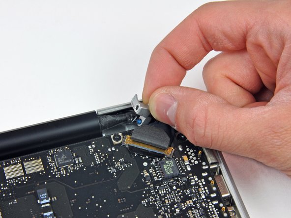
    • Grab the plastic pull tab secured to the display data cable lock and rotate it toward the DC-in side of the computer.

    • Pull the display data cable connector straight away from its socket.

    • Make sure to pull the connector parallel to the face of the logic board, not straight up from its socket.

  22. Questo passaggio è privo di traduzione. Aiuta a tradurlo

    : passo 22, immagine 1 di 2 : passo 22, immagine 2 di 2
    • Using the tip of a spudger, flip up the keyboard backlight ribbon cable retaining flap.

    • Pull the keyboard backlight ribbon cable straight out of its socket.

  23. Questo passaggio è privo di traduzione. Aiuta a tradurlo

    : passo 23, immagine 1 di 1
    • Remove the following screws:

    • Eight 3.5 mm T6 Torx screws securing the logic board to the upper case.

    • Two T6 Torx screws securing the DC-In board to the upper case.

    • Do not remove the logic board yet! There are connectors attached to the underside of the logic board that must first be disconnected.

  24. Questo passaggio è privo di traduzione. Aiuta a tradurlo

    : passo 24, immagine 1 di 1
    • Carefully lift the logic board assembly from the left side and work it out of the upper case, minding the port side that may get caught during removal.

    • Do not entirely remove the logic board yet!

    • Ensure that the logic board is free from all connections to the upper case (except the battery connector) before proceeding.

  25. Questo passaggio è privo di traduzione. Aiuta a tradurlo

    : passo 25, immagine 1 di 2 : passo 25, immagine 2 di 2
    • Lift the logic board enough to gain clearance and use a spudger to pry the microphone up off the upper case.

    • Slide the logic board away from the port openings and lift the assembly out of the upper case.

    • Before reinstalling the logic board, it is easiest to press the microphone down into its housing in the left speaker to keep it in place.

  26. Questo passaggio è privo di traduzione. Aiuta a tradurlo

    : passo 26, immagine 1 di 1
    • Disconnect the DC-In Board connector from the logic board by pulling it straight away from its socket.

Linea Traguardo

Altre 32 persone hanno completato questa guida.

0 Commenti

Aggiungi Commento

Visualizza Statistiche:

Ultime 24 Ore: 2

Ultimi 7 Giorni: 5

Ultimi 30 Giorni: 18

Tutti i Tempi: 13,569