Questa versione può contenere modifiche errate. Passa all'ultima istantanea verificata.
Cosa ti serve
-
-
Premere con le dita entrambe le linguette di sgancio della batteria verso l'esterno e sollevare la batteria dal computer.
-
-
-
Rimuovere le tre viti con testa a croce da 2 mm dallo sportello della memoria.
-
Sollevare lo sportello della memoria affinché sia possibile prenderlo e farlo scorrere verso di sé, estraendolo dall'alloggiamento.
-
-
-
Rimuovere le due viti con testa a croce da 2,8 mm nello scomparto della batteria in prossimità della chiusura.
-
-
-
Sollevare il case dalla parte posteriore e, mediante le dita, liberarlo progressivamente dai lati. Dopo aver liberato i fianchi, potrebbe essere necessario inclinare il case verso l'alto e verso il basso per liberare la parte anteriore del case superiore.
-
Sono presenti quattro levette di plastica sopra lo slot del DVD e in alto e a sinistra del sensore infrarossi. Queste levette potrebbero essere difficili da sganciare senza fare leva. Inoltre, potrebbe essere difficile riagganciarle durante il riassemblaggio.
-
-
-
-
Utilizzare l'estremità piatta di un inseritore per scollegare il cavo piatto arancione dell'unità SuperDrive dalla scheda logica, rimuovendo il nastro secondo necessità.
-
-
-
Rimuovere le 4 viti seguenti:
-
Due viti con testa a croce argentate da 3,3 mm su entrambi i lati dell'unità SuperDrive.
-
Una vite Torx T6 argentata da 4,7 mm dall'angolo superiore sinistro dell'unità.
-
Una vite con testa a croce nera da 6,2 mm dall'angolo superiore destro dell'unità.
-
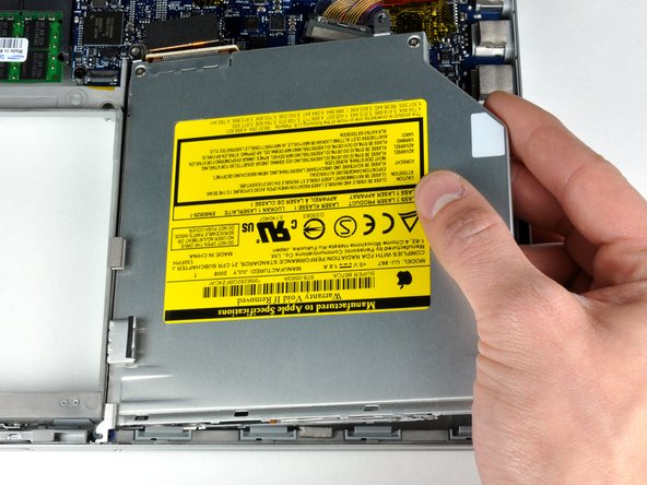
Sollevare l'unità ottica e rimuoverla dal computer.
-
-
Questo passaggio è privo di traduzione. Aiuta a tradurlo
-
Disconnect the hard drive and ExpressCard connectors from the left side of the logic board.
-
-
Questo passaggio è privo di traduzione. Aiuta a tradurlo
-
Disconnect the iSight and display data cables from the logic board by sliding them straight back out of their connectors, removing tape as necessary.
-
-
Questo passaggio è privo di traduzione. Aiuta a tradurlo
-
Disconnect the eight indicated connectors by placing a spudger beneath the wired side of each one and lifting up.
-
-
Questo passaggio è privo di traduzione. Aiuta a tradurlo
-
Remove the foam bumper from the top of the right hinge of the display.
-
-
Questo passaggio è privo di traduzione. Aiuta a tradurlo
-
Remove the silver 9.5 mm T6 Torx screw securing the ground loop in the display data cable to the casing.
-
-
Questo passaggio è privo di traduzione. Aiuta a tradurlo
-
Remove the single black 6 mm T6 Torx screw securing the upper portion of the logic board to the lower case.
-
-
Questo passaggio è privo di traduzione. Aiuta a tradurlo
-
Peel up the orange Kapton tape securing the right thermal sensor cable to the logic board.
-
-
Questo passaggio è privo di traduzione. Aiuta a tradurlo
-
Remove the following 15 screws:
-
One 4.4 mm black Phillips screw to the right of the ram slot.
-
Eight 4.7 mm silver T6 Torx screws securing the logic board to the lower case.
-
One 6.2 mm black T6 Torx screw on the right side of the left fan.
-
Five 9.4 mm silver T6 Torx screws securing the left and right fans.
-
-
Questo passaggio è privo di traduzione. Aiuta a tradurlo
-
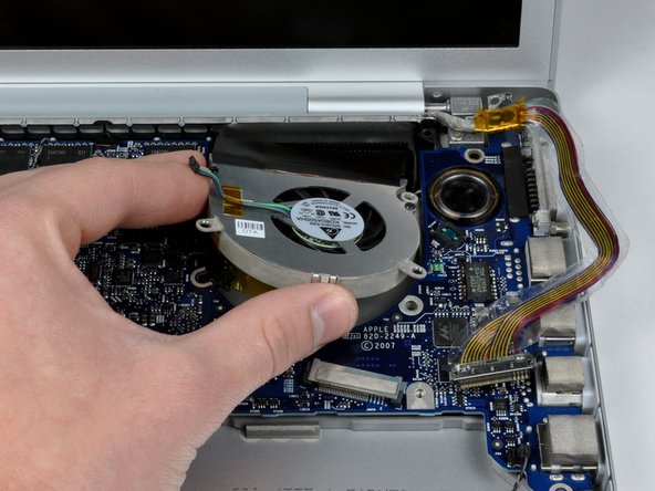
Hold the logic board down with one hand and use your other hand to lift the left fan up from its housing. There is a piece of black tape securing the left fan to the heat sink. Carefully peel this tape up from the heat sink as you lift the left fan up.
-
Lift the right fan up and carefully peel up the tape securing the fan to the heat sink as you go.
-
Remove the right fan from the computer.
-
-
Questo passaggio è privo di traduzione. Aiuta a tradurlo
-
Lift up the left side of the logic board and disconnect the gray and black power cable from the bottom of the board.
-
Grasp the logic board at the left side and at the thin section, and rotate the logic board out of the lower case.
-
-
Questo passaggio è privo di traduzione. Aiuta a tradurlo
-
Remove the two silver T6 Torx screws securing the battery connector to the lower case.
-
-
Questo passaggio è privo di traduzione. Aiuta a tradurlo
-
Disconnect the large gray and black battery connector cable from the left I/O board.
-
-
Questo passaggio è privo di traduzione. Aiuta a tradurlo
-
Thread the gray and black power cable beneath the speaker cable, and lift the battery connector out of the computer.
-


Annulla: non ho completato questa guida.
Altre 12 persone hanno completato questa guida.
